Solved Examples
Example 31.1
A capacitor gets a charge of 60 muC when it is connected to a battery of emf 12 V. Calculate the capacitance of the capacitor.
Sol.
The potential difference between the plates is the same as the emf of the battery which is 12 V. Thus, the capacitance is

Example 31.3
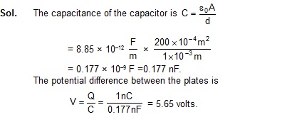
Calculate the capacitance of a parallel–plate capacitor having 20 cm × 20 cm square plates separated by a distance of 1.0 mm.
Sol.
The capacitance is

Example 31.4
Calculate the charge on each capacitor shown in figure .
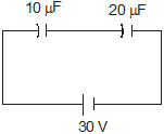
In series combination, each capacitor has equal charge and this charge equals the charge suppled by the battery. Thus, each capacitor has a charge of 200 muC.
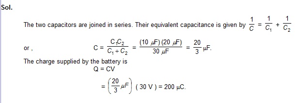
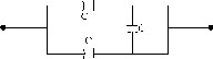
Example 31.5 Find the equivalent capacitance of the combination shown in figure between the points P and N.
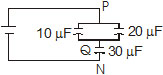
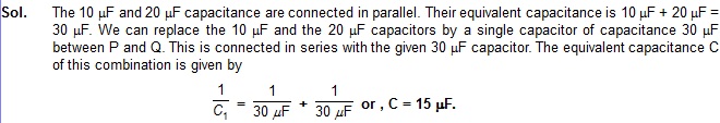
Example 31.6 Find the equivalent capacitance of the combination shown in the figure between the points P and N.
Sol. Let us connect a battery between the points P and N. The charges and the potentials are shown in figure.The positive terminal of the battery supplies a charge +Q which appears on the plate A 1 . The facing plate A 2 gets a charge – Q. The plates A 2 , A 3 and A 5 taken together form an isolated system. The total charge on these three plates should be zero. Let a charge Q 1 appear on A 3 , then a charge Q – Q 1 will appear on A 5 to make the total charge zero on the three plates. The plate A 4 will get a charge – Q 1 (facing plate of A 3 ) and A 0 will get a charge – ( Q–Q 1 ) (facing plate of A 5 ). The total charge – Q on A 4 and A 6 is supplied by the negative terminal of the battery. This completes the charge distribution.
Next, suppose the potential at the point N is zero and at P it is V. The potential of the plate A 4 and A 6 is also zero. The potential of the plate A 1 is V. The plates A 2 , A 3 and A 5 are at the same potential. Let this common potential be V 1 . This completes the potential distribution.
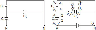
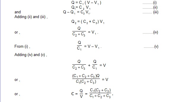
Applying the capacitor equation Q = CV to the three capacitors ,
Example 31.7 Find the energy stored in a capacitor of capacitance 100muF when it is charged to a potential difference of 20 V.
Sol. The energy stored in the capacitor is

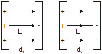
The energy stored in a capacitor is electrostatic potential energy. When we pull the plates of capacitor apart, we have to do work against the electrostatic attraction between the plates. In which region of space is energy stored ? When we increase the separation between the plates from d 1 to d 2 , an amount Q2/2Ae0 (d 2 – d 1 ) of work is performed by us and this much energy goes into the capacitor. On the other hand, new electric field is created in a volume A (d2 – d1 ) figure. We conclude that the energy Q2/2Ae0 (d2 – d1 ) is stored in the volume A(d2 – d1 ) which is now filled with the electric field. Thus, an electric field has energy associated with it. The energy stored per unit volume in the electric field is

where E is the intensity of the electric field.
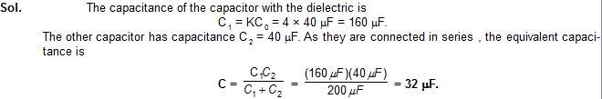
Example 31.8 Two parallel–plate capacitors, each of capacitance 40 muF, are connected in series. The space between the plates of one capacitor is filled with a dielectric material of dielectric constant K = 4. Find the equivalent capacitance of the system.
Example 31.9
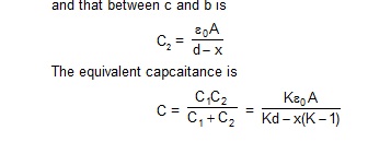
A parallel–plate capacitor has plate area A and plate separation d. The space between is filled up to a thickness x (< d) with a dielectric constant K. Calculate the capacitance of the system.
Sol. 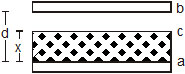
The situation is shown in figure. The given system is equivalent to the series combination of two capacitors, one between a and c and the other between c and b. Here c represents the upper surface of the dielectric. This is because the potentialat the upper surface of the dielectric is constant and we can imagine a thin metal plate being placed there.
The capacitance of the capacitor between a and c is

Questions for Short answer
1. Suppose a charge +Q1 is given to the positive plate and a charge – Q2 to the negative plate of a capacitor. What is the "Charge on the capacitor" ?
2. As C (1/V) = Q, can you say that the capacitance C is proportional to the charge Q ?
3. A hollow metal sphere and a solid metal sphere of equal radii are given equal charges. Which of the two will have higher potential ?
4. The plates of a parallel–plate capacitor are given equal positive charges. What will be the potential difference between the plates ? What will be the charges on the facing surface ? On the outer surfaces ?
5. A capacitor has capacitance C. Is this information sufficient to know what maximum charge the capacitor can contain ? If yes, what is this charge ? If no, what other information is needed ?
6. The dielectric constant decreases if the temperature is increased. Explain this in terms of polarization of the material.
7. When a dielectric slab is gradually inserted between the plates of an isolated parallel–plate capacitor, the energy of the system decreases. What can you conclude about the force on the slab exerted by the electric field ?
Objective - I
1. A capacitor of capacitance C is charged to a pontential V. The flux of the electric field through a closed surface enclosing the capacitor is
![]()
2. Two capacitors each having capacitance C and breakdown voltage V are joined in series. The capacitance and the breakdown voltage of the combinate will be
(A) 2 C and 2 V (B) 2/C and 2/V (C) 2 C and 2/V (D) 2/C and 2 V
3. If the capacitors in the previous question are joined in paralle, the capacitance and the breakdown voltage of the combination will be
(A) 2 C and 2 V (B) C and 2 V (C) 2 C and V (D) C and V
4. The equivalent capacitance of the combination shown in figure is -
(A) C (B) 2 C (C) C/2 (D) none of these
5. A dielectric slab is inserted between the plates of an isolated capacitor. The force between the plated will
(A) increase (B) decrease (C*) remain unchanged (D) become zero
6. The energy density in the electric field created by a point charge falls off with the distance from the point charge as
(A) 1/r (B) 1/r2 (C) 1/r3 (D) 1/r4
7. A parallel-plate capacitor has plates of unequal of unequal area. The large plate is connected to the positive terminal of the battery and the smaller plate to its neagtive terminal. Let Q+ and Q– be the charges apperaing on the positive and the negative plates respectively.
(A) Q+ > Q–. (B*) Q+ = Q–. (C) Q+ < Q–.
(D) The infromation is not sufficent to decide the relation between Q+ and Q-.
8. A thin metal plate P is inserted between the plates of a parallel-plate capacitor of capacitance C in such a way that its edges touch the two plates (fig.). The capacitance now becomes -

(A) C/2 (B) 2 C (C) 0 (D*) ¥
9. Fig. shows two capacitors connected in series and joined to a bettery. The graph shows the variation in pontential as one moves from left to right on the branch containing the capacitors -
(A) C1 > C2. (B) C1 = C2. (C*) C1 < C2.
(D) The information is not sufficient to decide the relation between C1 and C2.
10. Two metal plates having charges Q, - Q face each other at some separation and are dipped into an oil tank. If the oil is pumped out, the electric field between the plates will -
(A) increase (B) decrease (C) remain the same (D) become zero
11. Two spheres of capacitances C1 and C2 carry some charges. They are put in contact and then separated. The final charges Q1 and Q2 on them will satisfy.
(A) Q1/Q2< C1/C2 (B) Q1/Q2 = C1/C2 (C) Q1/Q2 > C1/C2 (D) Q1/Q2 = C2/C1
Objective - II
1. The capacitance of a capacitor does not depend on
(A) the shape of the plates (B) the size of the plates
(C) the charges on the plates (D) the separation between the plates.
2. A dielectric slab is inserted between the plates of an isolated charged capacitor. Which of the following quantites will remain the same ?
(A) The electric field in the capacitor (B) the charge on the capacitor
(C) the potential differencr between the plates (D) the stored energy in the capacitor
3. A dielectric slab is inserted between the plates of a capacitor. The charge on the capacitor is Q and the magnitude of the induced charge on each surface of the dielectric is Q’.
(A) Q’ may be larger than Q. (B) Q’ must be large than Q.
(C) Q’ must be equal than Q. (D) Q’ must be smaller than Q.
4. Each plate of a parallel plate capacitor has a charge q on it. The capacitor is now connected to a battery. Now,
(A) the facing surfaces of the capacitor have equal and opposite charges.
(B) the two plates of the capacitor have equal and opposite charges.
(C) the battery supplies equal and oppostie charges to the two plates.
(D) the outer surface of the plates have equal charges.
5. The separation between the plates of a charged parallelplate capacitor is increased. Which of the following quantities will charge ?
(A) charge on the capacitor (B) potential difference across the capacitor
(C) energy of the capacitor (D) energy density between the plates.
6. A parallel-plate capacitor is connected to a battery. A metal sheet of negligable thickness is placed between the plates. The sheet remains parallel to the plates of the capacitor.
(A) The battery will supply more charge
(B) The capacitance will increase.
(C) The potnetial difference between the plates will increase
(D) Equal and opposite charges will appear on the two faces of the metal plate.
7. Following operations can be performed on a capacitor:
X - connect the capacitor to a battery of emf w.
Y - disconnect the battery
Z - reconnect the battery with polarity reversed
W - insert a dilectric slab in the capacitor
(A) In XYZ (peroform X, then Y, then Z) the stored electric energy remains unchanged and no termal energy is developed.
(B) The charge appearing on the capacitor is greater after the action XWY than after the action XYW
(C) The electric energy stored in the capacitor is greater after the action WXY than after the action XYW. (D) The electric field in the capacitor after the action XW is the same as that after WX.
Worked Out Examples
1. A parallel-plate capacitor has plates of area 200 cm2 and separation between the plates 1.00 mm. What potential difference will be developed if a charge of 1.00 nC (i.e., 1.00 × 10⁻⁹ C) is given to the capacitor? If the plate separation is now increased to 2.00 mm, what will be the new potential difference?
2. An isolated sphere has a capacitance of 50 pF. (a) Calculate its radius. (b) How much charge should be placed on it to raise its potential to 104V?
Sol. (a) The capacitance of an isolated sphere is C = 4pe0R. Thus,
50 × 10–12 F = R/9 x 109m/F
or, R = 50 × 10–12 × 9 × 109 m = 45 cm.
(b) Q = CV
= 50 × 10–12 F × 104 V = 0.5 muC.
3. Consider the connections shown in figure (a) Find the capacitance between the points A and B. (b) Find the charges on the three capacitors. (c) Taking the potential at the point B to be zero, find the potential at the point D.
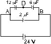
As the potential at the point B is taken to be zero, the potential at the point D is 16 V.
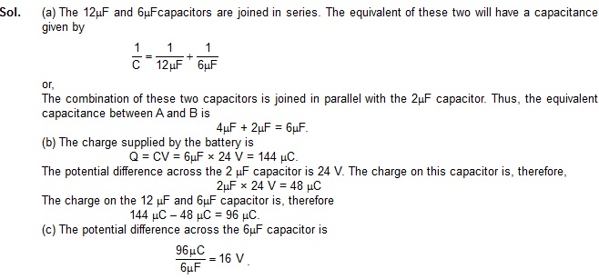
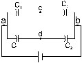
4. If 100 volts of potential difference is applied between a and b in the circuit of figure, find the potential difference between c and d.
Sol. The charge distribution on different plates is shown in figure. Suppose charge Q1 + Q2 is given by the positive terminal of the battery, out of which Q1 resides on the positive plate of capacitor (1) and Q2 on that of (2). The remaining plates will have charges as shown in the figure.
Take the potential at the point b to be zero. The potential at a will be 100 V. Let the potentials at points c and d be Vc and Vd respectively. Writing the equation Q = CV for the four capacitors, we get,
100 V – Vc = Vc – Vd
or, 2Vc – Vd = 100 V ..............(v)
and from (iii) and (iv),
Vc – Vd = Vd
or, Vc = 2Vd. ..............(vi)
From (v) and (vi),
Vd = 100/3 V and Vc = 200/3V
so that Vc – Vd = 100/3V .
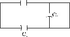
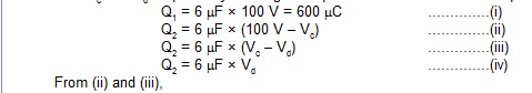
5. Find the charges on the three capacitors shown in figure
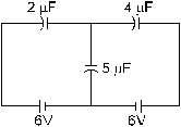
Sol. Take the potential at the junction of the batteries to be zero. Let the left battery supply a charge Q1 and the right battery of a charge Q2. The charge on the 5mF capacitor will be Q1 + Q2. Let the potential at the junction of the capacitors be V1. The charges at different plates and potentials at different point are shown in figure
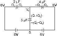
Note that the charges on the three plates which are in contact add to zero. It should be so, becasue, these plates taken together form an isolated system which cannot receive charges from the batteries. Applying the equation Q = CV to the three capacitors, we get,

Ans. 24 muC, 48 muC, 72 muC
Sol. Suppose, the capacitor C3 is removed from the given system and a battery is connected between a and b. The remaining sustem is shown in figure. From the symmetry of the figure, the potential at c will be the same as the potential at d. Thus, if the capacitor C3 is connected between c and d, it will have no charge. The charge of all the remaining four capacitors will remain unchanged. Thus, the system of capacitors in figure is equivalent to that in the figure. The equivalent capacitance of the system in figure can be calculated by applying the formulae for series and parallel combinations. C1 and C2 are connected in series. Their equivalent capacitance is

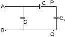
7. Find the equivalent capacitance between the point A and B in figure
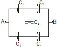
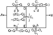
Sol. Let us connect a battery between the points A and B. The change distribution is shown in figure. Suppose the positive terminal of the battery supplies a charge +Q and the negative terminal a charge –Q. The charge Q is divided between plates a and e. A charge Q1 goes to the plate a and the rest Q – Q1 goes to the plate e. The charge – Q supplied by the negative terminal is divided between plates d and h. Using the symmetry of the figure, charge –Q1 goes to the plate h and –(Q–Q1) to the plate d. This is because if you look into the circuit from A or from B, the circuit looks identical. The division of charge on the other plates may be written easily. The charge on the plate i is 2Q1 – Q which ensures that the total charge on plates b, c and i remains zero as these three plates form an isolated system.
We have,
VA – VB = (VA – V0) + (VD – VB)
![]()
Also VA – VB = (VA – VD) + (VD – VE) + (VE – VB)
![]()
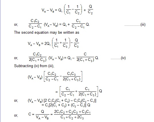
We have to eliminate Q1 from these equations to get the equivalent capacitance Q/(VA – VB).
The first equation may be written as
8. Twelve capacitors, each having a capacitance C, are connected to form a cube figure. Find the equivalent capacitance between the diagonally opposite corners such as A and B.
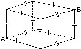
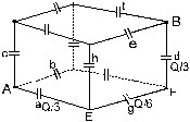
Sol. Suppose the points A and B are connected to a battery. The charges appearing on some of the capacitors are shown in figure. Suppose the positive terminal of the battery supplies a charge + Q therough the point A. The charge is divided on the three plates connected to A. Looking from A, the three sides of the cube have identical properties and hence, the charge will be equally distributed on the three plates. Each of the capacitors a, b and c will receive a charge Q/3.
The negative terminal of the battery supplies a charge –Q through the point B. This is again divided equally on the three plates connected to B. Each of the capacitors d, e and f gets equal equal charge Q/3.
Now consider the capacitors g and h. As the three plates connected to the point E form an isolated system, their total charge must be zero. The negative plate of the capacitor a has a charge –Q/3. The two plates of g and h connected to E should have a total charge Q/3. By symmetry, these two plates should have equal charges and hence each of these has a charge Q/6.
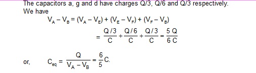
The capacitors a, g and d have charges Q/3, Q/6 and Q/3 respectively.
We have
9. The negative plate of a parallel plate capacitor is given a charge of –20 × 10–8C. Find the charge appearing on the four surfaces of the capacitor plates.
Sol. 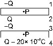
Let the charge appearing on the inner surface of the negative plate be –Q. The charge on its outer surfaces will be Q – 20 × 10–8C.
The charge on the inner surfaceof the positive plate will be + Q from Gauss’s law and that on the outer surface will be –Q as the positive plate is electrically neutral. The distribution is shown in figure.
To obtain the value of Q consider the lectric field at a point P inside the upper plate.
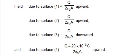
As P is a point inside the conductor, the field here must be zero. Thus,
Q = –Q + 20 × 10–8 C
or, Q = 10 × 10–8 C.
The charge on the four surfaces may be written immediately from figure.
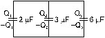
The 36 mC charge on the three positive plates now redistribute as Q1, Q2 and Q3 on the three connected positive plates. Similarly,
–36 muC redistributes as –Q1, –Q2 and Q3. The three positive plates are now at a common potential and the three negative plates
are also at a common potential. Let the potential difference
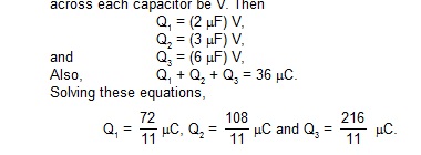 .
.
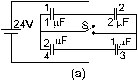
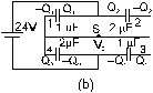
11. The connections show in figure are established with the switch S open. How much charge will flow through the switch if it is closed?
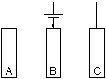
12. Each of the three plates shown in figure has an area of 200 cm2 on one side and the gap between the adjacent
plates is 0.2 mm. The emf of the battery is 20 V. Find the distribution of change on various surfaces of the plates.
What is the equivalent capacitance of the system between the terminal points?
Sol. Suppose the negative terminal of the battery gives a change –Q to the plate B. As the situation is symmetric
on the two sides of B, the two faces of the plate B will share equal changes –Q/2 each. From Gauss’s law, the
facing surfaces will have changes Q/2 each. As the positive terminal of the battery has supplied just thus much
change (+Q) to A and C, the outer surfaces of A and C will have no change. The distribution will be as shown in figure.
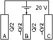
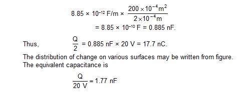
The capacitance between the plates A and B is
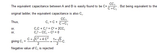
13. Find the capacitance of the infinite ladder shown in figure
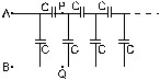
Sol. As the ladder is infinitely long, the capacitance of the ladder to the right of the points P, Q is the same as that of the
ladder to the right of the points A, B. If the equivalent capacitance of the ladder is C1, the given ladder may be replaced
by the connections shown in figure
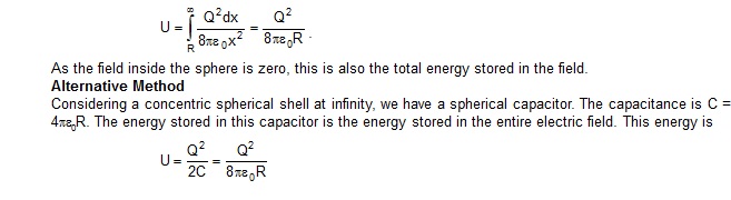
14. Find the energy stored in the electric field produced by a metal sphere of radius R containing a charge Q.
Sol. Consider a thin spherical shell of radius x(>R) and thickness dx concentric with the given metal sphere. The energy density in the shell is
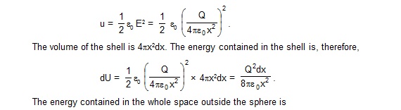
.