WORKED OUT EXAMPLES
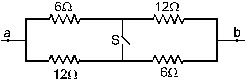
13. Find the equivalent resistance between the points a and b of the network shown in figure.
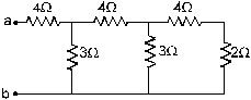
Sol. The two resistor 4W and 2W at the right end are joined in series and may be replaced by a single resistor of 6W. This 6W is connected with the adjacent 3W resistor in parallel. The equivalent resistance of these two is 6 ohm × 3 ohm / 6 ohm + 3 ohm = 2ohm.
This is connected in series with the adjacent 4 ohm resistor giving an equivalent resistance of 6 ohm which is connected i parallel with the 3 ohm resistor. Their equivalent resistance is 2 ohm which is connected in series with the first 4 ohm resistor from left. Thus, the equivalent reistance between and b is 6 ohm.
14. Find the effective resistors between the points A and B in figure.
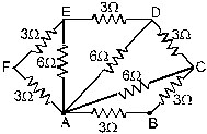
Sol. The resistors AF and FE are in series. Their equivalent is 3ohm + 3ohm = 6 ohm. This is connected in parallel with AE. Their equivalent between A and E is, therefore. 6 ohm × 3 ohm / 6ohm + 3 ohm = 3ohm. This 3W resistance between A and E is the series with ED and the combination is in parallel with AD. Their equivalent between A and D is again 3ohm.
Similarly, the equivalent of this 3W, DC and AC is 3ohm. This 3ohm is in series with CB and the combination is in parallel with AB. The equivalent resistance between A and B is, therefore.
6 ohm × 3 ohm / 6 ohm + 3 ohm = 2W.
15. Find the equivalent resistance of the network shown in figure between the points a and b when (a) the switch S is open (b) the switch S is closed.
Sol. (a) When the switch is open, 6ohm and 12ohm resistors on the upper line are in series giving an equivalent of 18ohm. Similarly, the resistors on the lower line have equivalent resistance 18ohm. These two 18ohm resistances are connected in parallel between a an db so that the equivalent resistance is 9ohm.
(b) When the switch is closed, the 6ohm and 12 ohm resistors on the left are in parallel giving an equivalent resistance of 4ohm. Similarly the two resistors on the right half are equivalent to 4ohm. These two are connected in series between a and b so that the equivalent resistance is 8ohm.
16. Each resistor shown in figure has a resistance of 10ohm and the battery has an emf of 6v. Find the current supplied by the battery.
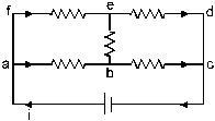
Sol. Suppose a current i starts from the position terminal of the battery. By symmetry, it divides equally in the resistors ab and fe, so that each of these carries a current i/2. The current going into the negative terminal is also i and by symmetry, equal currents should come from ed and bc. Thus, the current in ed is also i/2 and hence there will be no current in eb.
Va – VC = (Va – Vb) + (Vb – Vc)
or, 6V = ×10ohm + ×10ohm
giving i = 0.6 A.
This is balanced wheat stone bridge.
17. Find the equivalent resistance of the network shown in figure between the points A and B.
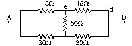
Sol. Suppose an ideal battery of emf e is connected across the point A and B. The circuit is a Wheatstone bridge with the galvanometer replaced by a 50 ohm resistance. As the bridge is balanced (R1/R2 = R3/R4), there will be no current through the 50ohm resistance. We can just remove the 50ohm resistance without changing any other current. The circuit is then equivalent to two resistances 30ohm and 60Wconnected in parallel. The equivalent resistance is
R = (30ohm)×(60ohm)/(30ohm)+(60ohm)=20ohm
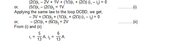
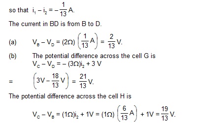
18. In the circuit shown in figure E,F,G and H are cells of emf 2,1,3 and 1V respectively. The resistances 2,1,3 and 1ohm are their respective internal resistances. Calculate (a) the potential difference between B and D and (b) the difference across the terminals of each of the cells G and H.
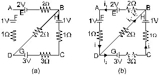
Sol. Suppose a current i1 goes in the branch BAD and a current i2 in the branch DCB. The current in DB will be i1 – i2 from the junction law. The circuit with the currents shown is redrawn in figure. Applying the loop law to BADB we get,
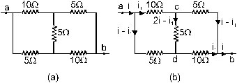
19. Find the equivalent resistance between the points a and bof the circuit shown in figure.
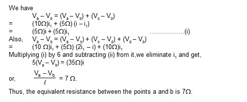
Sol. Suppose a current i enters the circuit at the point a,a part i1 goes through the 10W resistor and the rest i – i1 through the 5W resistor. By symmetry, the current i coming out from the point b will be composed of a part i1 from the 10 ohm resistor and i –i1 from the 5 ohm resistor. Applying Kirchoff’s junction law, we can find the current through the middle 5 ohm resistor. The current distribution is shown in figure.
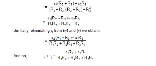
20. Find the currents going through the resistors R1,R2 and R3 in the circuit of figure.
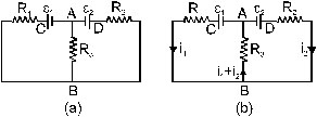 Sol. Let us take the potential of the points A to be zero. The potential at C will be S1 and that at D will be S2. Let the potential at B be V. The currents through the three resistors are i1, i2 and i1+i3 as shown in figure. Note that the current directed towords B equals the currents directed away from BApplying Ohhm's law to the three resistors R1,R2 nd R3 we get e1- V = R1i1 .....................(i) e2- V= R2i2 ...................(ii) V-0 = R3(i1+i2) ..................(iii)
Adding (i) and (ii)
e1 = R1i1 + R3(i1 + i2)
= (R1 + R3)i1 + R3i2 ,,,,,,,,,,,,,,,,,,(iv)
and adding (ii) and (iii),
e2 = R2i2 + R3(i1 + i2)
= (R2 + R3)i2 + R3i1. ...................(v)
Equations (iv) and (v) may be directly written from Kirchoff’s loop law applied to the left and the right half of the circuit.
Multiply (iv) by (R2 + R3), (v) by R3 and subtract to eliminate i2. This gives
21. Find the equivalent resistance between the points a and c of the network shown in figure. Each resistance is equal to r.
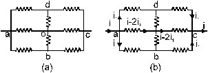
Sol. Suppose a potential difference V is applied between a and c so that a current i enters at a and the same current leaves at c.The current i divides in three parts at a. By symmetry the part in ad and in ab will be equal. Let each of these current be i1. The currents through a is i – 2i1. Similarly, currents from dc, bc and of combine at c to given the total current i. Since the situation at c is equivalents to that at a, by symmetry, the currents in dc and bc will be i1 and that in oc w i – 2i1.
Applying Kichhoff’s junction law at d, we see that the current in do is zero. Similarly, the current in ob is zero. We can remove do and obfor further analysis. It is then equivalent to three resistance, each of value 2r, in parallel. The equivalent resistance is, therefore, 2r/3.
22. Twelve wires, each having resistance r,a re joined to form a cube as shown in figure. Find the equivalent resistance between the ends of a face diagonal such as a and c.
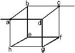
Sol. Suppose a potential difference V is applied between the points a and c so that a current i enters at a and the same current leaves at c.The current distribution is shown in figure.
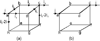
By symmetry, the paths ad and ab are equivalent and hence will carry the same current i1. The path a will carry the remaining current i – 2i1 (using Kichhoff’s junction law). Similarly at junction c, currents coming from dc and bc will be i1 each and from fc will be i – 2i1 Kirchhoff’s junction law at b and d shows that currents through be and dg will be zero and hence we may be igonires for further analysis. Omitting these two wires, the circuit is redrawn in figure.
The wire hef and hgf are joined in parallel and have equivalent resistance (2r) (2r) / (2r) + (2r) = r between h and f. this is joined in series with an and fc giving equivalent resistance r+r+r = 3r. This 3r is joined in parallel with adc (2r) and abc (2r) between a and c.
therefore, given by 1/R= 1/3r + 1/2r + 1/2r
giving R = (3/4)r
23. Find the equivalent resistance of the circuit of the previous problem between the ends of an edge such as a and b in figure.
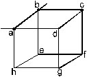
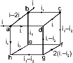
Sol. Suppose a current i enters the circuit at the point a and the same current leaves the circuit at the point b. The current distribution is shown in figure. The paths through ad and ah are equivalent and carry equal current i1. The current through ab is then i – 2i1.
The same distribution holds at the junction b. Currents in eb and cb are i1 each. The current i1 in ah is divided into a part i2 in he and i1 – i2 in hg. Similar is the division of current i1 in ad into dc and dg. The rest of the currents may be written easily using Kirchhoff’s junction law. The potential difference V between a and b may be written from the paths ab, aheb and ahgfcb as
V = (i – 2i1)r
V = (i1 + i2 + i1)r
and V = [i1 + (i1 – i2) + 2(i1 – i2) + (i1 – i2) + i1]r
which may be written as
V = (i – 2i1)r
V = (2i1 – i2)r
andV = (6i1 – 4i2)r.
Eliminating i1 and i2 from these equations,
V/i = 7/12r
which is the equivalent resistance.
24. Find the equivalent resistance between the points a and b of the infinite ladder shown in figure
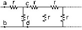
Sol. Let the equivalent resistance between a and b be R. As the ladder is infinite, R is also the equivalent resistance of the ladder to the right of the point c and d. Thus, we can replace the part to the right of cd by a resistance R and redraw the circuit as in figure

This gives
R = r + rR/ r + R
or, rR + R2 + r2 + 2rR
or, R2 – rR – r2 = 0

25. Find the equivalent resistance of the network shown in figure, between the points a and b.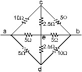
Sol. Suppose a current i enters the network at point a and the same current leaves it at point b. Suppose, the currents in ac, ad and ae are i1, i2 and i3 respectively. Similar will be the distribution of current at b. The current i leaving at b is composed of i1 from db, i2 from cb and i3 from eb. The situation is shown in figure.
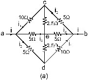
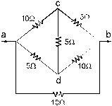
As the current in ae is equal to that in eb, the current in ce will be equal to the current in ed from the junction law. If we assume that thebranches ced and aeb do not physically touch at e, nothing will changed in the current distribution. We can then represent the branch aeb by a single resistance of 10W connected between a and b. Similarly, the branch ced may be replaced a single 5W resistor between c and d.The circuit is redrawn in figure. Thus us same as the circuit in figure connected in parallel with a resistance of 10W. So the network is equivalent to a parallel combination of 7W and 10W resistor. The equivalent resistance of the whole network is, therefore,
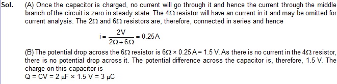
26. (A) Find the current i supplied by the battery in the network shown in figure in steady state. (B) Find the charge on the capacitor. 
27. A part of a circuit in steady state along with the currents flowing in the branches, the values of resistancess etc,is shown in figure. Calculate the energy stored in the capacitors.
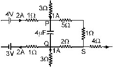
Sol. To get the energy stored the capacitor, we shall calculate the potential difference between the points P and Q. In study state, there is no current in the capacitor branch. Applying Kirchhoff’s junction law at P, the current i the 5 ohm – 1ohm branch will be 3A and hence VP – VS = 6 ohm × 3A = 18V, Applying the same theorem at Q, the current in the 2 ohm resistor will be 1A towards Q so that
VS – VQ = 2Q × 1A = 2V
Thus, VP – VQ = (VP – VS) + (VS – VQ) = 20 V
28. (A) Find the potential drops across the two resistors shown in figure. (B) A voltmeter of resistance 600W is used to measure the potential drop across the 300W resistor. What will be the measured potential drop ?
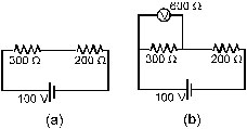
Sol. The current in the circuit is 100V/300 ohm + 200 ohm = 0.2 A. The potential drop across the 300 W resistor is 300 W × 0.2 A = 60 V.
Similarly, the drop across the 2 ohm resistor is 40 V.
(b) The equivalent resistance, when the voltmeter is connected across 300 ohm , is
R = 200 ohm +600 ohm × 300 ohm/ 600 ohm + 300 ohm = 400 ohm
Thus, the main current from the battery is
i = 100V/400 ohm = 0.25 A
The potential drop across the 200 W resistor is therefore, 200 W × 0.25 A = 50V and that across 300 ohm is also 50V. This is also the potential drop across the voltmeter and hence the reading of the voltmeter is 50 V.
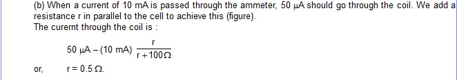
29. A galvanometer has a coil of resistance 100 ohm showing a full-scale deflection at 50A. What resistance should be added to use it as (a) a voltmeter of range 50V (b) an ammeter of range 10 mA ?
Sol. (a) When a potential difference of 50 V is applied across the voltmeter, full-scale deflection should take place. Thus, 50A should go through the coil. We add a resistance R in series with the given coil to achieve this
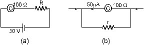
We have,
50A = 50V/ 100 ohm + R
or, R = 106 ohm – 100ohm = 106 ohm.
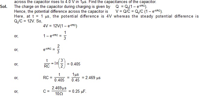
31. A capacitor is connected to a 12 V battery through a resistance of 10W. It is found that the potential difference
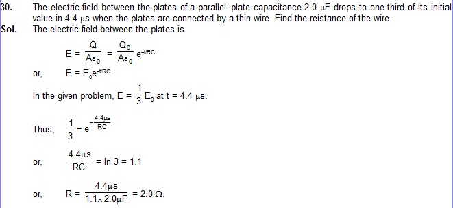
32. A capacitor charged to 50 V is discharged by connecting the two plates at t = 0. If the potential difference across the plates drops to 1.0 V at t = 10 ms, what will be the potential difference at t = 20 ms ?