
Exercise
1. The amount of charge passed in time t through a cross-section of a wire is
Q(t) = At2 + Bt + C
(a) Write the dimensional formulae for A, B and C
(b) If the numerical values of A, B and C are 5, 3 and 1 respectively in SI units, find the value of the current at t = 5 s.
2. An electron gun emits 2.0 × 10¹⁶ electrons per second. What electric current does this correspond to?
Ans. 3.2 × 10⁻³ A
3. The electric current existing in a discharge tube is 2.0 µA. How much charge is transferred across a cross-section of the tube in 5 minutes?
4. The current through a wire depends on time as i = i0 + Alpha t, where i0 = 10 A and Alpha = 4 A/s. Find the charge crossed through a section of the wire in 10 seconds.
Ans. 300 C
5. A current of 1.0 A exists in a copper wire of cross-section 1.0 mm2. Assuming one free electron per atom calculate the drift speed of the free electrons in the wire. The density of copper is 9000 km/m3.
Ans. 0.074 mm/s
6. A wire of length 1 m and radius 0.1 mm has a resistance of 100 ohm. Find the resistivity of the material.
Ans. pi × 10–6 ohm-m.
7. A uniform wire of resistance 100 ohm is melted and recast in a wire of length double that of the original. What would be the resistance of the wire ?
8. Consider a wire of length 4m and cross-sectional area 1 mm2 carrying a current of 2A. If each cubic metre of the material contains 1029 free electrons, find the average time taken by an electrons to cross the length of wire.
Ans. 3.2 × 10⁴ s » 8.9 hours.
9. What length of a copper wire of cross-sectional area 0.01 mm2 will be needed to prepare a resistance of 1k ohm? Resistivity of copper = 1.7 × 10⁻⁸ ohm-m.
Ans. 0.6 km.
10. Figure shows a conductor of length l having a circular cross-section. The radius of cross-section varies linearly from a to b. The resistivity of the material is r. Assuming that b – a << l. find the resistance of the conductor.
![]()
11. A copper wire of radius 0.1 mm and resistance 1 k ohm is connected across a power supply of 20 V. (a) How many electrons area transferred per second between the supply and the wire at one end? (b) Write down the current density in the wire.
Ans. (a) 1.25 × 10¹⁷ (b) 6.37 × 10⁸ A/m2 .
12. Calculate the electric field in a copper wire of cross-sectional area 2.0 mm2 carrying a current of 1A. The resistivity of copper = 1.7 × 10⁻⁵ ohm-m.
13. A wire has a length of 2.0 m and a resistance of 5.0 ohm. Find the electric field existing inside the wire if it carries a current of 10 A.
Ans. 25 V/m.
14. The resistance of an iron wire and a copper wire at 200C are 3.9 ohm and 4.1 ohm respectively. At what temperature will the resistances be equal ? Temperature coefficient of resistivity for iron is
5.0 × 10⁻³ K–1 and for copper it is 4.0 × 10⁻³ K–1 and for copper it is 4.0 × 10⁻³ K–1 and for copper it is 4.0 × 10⁻³ K–1 . Neglect any thermal expansion.
15. The current in a conductor and the potential difference across its ends are measures by an ammeter and a voltmeter. The meters draw negligible currents. The ammeter is accurate but the voltmeter has a zero error (that is , it does read zero when no potential difference is applied). Calculate the zero error if the readings for two different conditions are 1.75 A, 14.4 V and 2.75 A, 22.4 V.
Ans. 0.4 volt
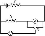
16. Figure shows an arrangement to measure the emf e and internal resistance r of a battery. The voltmeter has a very high resistance and the ammeter also has some resistances. The voltmeter reads 1.52 V when the switch S is open. When the switch is closed the voltmeter reading drops is to 1.45 V and the ammeter reads 1.0 A. Find the emf and the internal resistance of the battery ?
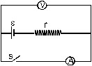
Ans. 1.52 V, 0.07 ohm
17. The potential difference between the terminals of a battery of emf 6.0 V and internal resistance 1ohm drops to 5.8 V when connected across an external resistor. Find the residences of the external resistor.
Ans. 29 ohm
18. The potential difference between the terminals of a 6.0 V battery is 7.2 V when it is being charged by a current of 2.0 A. What is the internal resistance of the battery ?
Ans. 0.6 ohm
19. The internal resistance of an accumulator battery of emf 6V is 10 ohm when it is fully discharged. As the battery gets charged up, its internal resistance decreases to 1 ohm. The battery in its completely discharged state is connected to a charger which maintains a constant potential difference of 9V. Find the current through the battery (a) just after the connections are made and (b) after a long time when it is competitively charged.
Ans. (a) 3/10 A = 0.3 A (b) 3A
20. Find the value of i1/i2 in figure if (a) R = 0.1 ohm, (b) R = 1ohm (c) R = 10 ohm. Note from your answer that in order to get more current from a combination of two batteries they should be joined in parallel if the external resistance is small and in series if the external resistance is large as compared to the internal resistances.
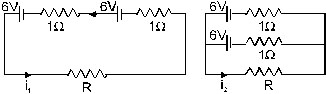
Ans. (a) 1.2/2.1 = 0.57 (b) 1 (c) 10.5/6 = 1.75
21. Consider N = n1n2 identical cells, each of emf e and internal resistance r. Suppose n1 cells ar joined in series to form a line and n2 such lines are connected in parallel. The combination drives a current in an external resistance R. (a) Find the current in the external resistance. (b) Assuming that n1 and n2 can be continuously varies, find the relation between n1,n2 R and r for which the current in R is maximum.
22. A battery of emf 100 V and a resistor of resistance 10k ohm are joined in series. This system is used as a source to supply current to an external resistance R if R not greater than 100 ohm then the current through it is constant upto two significant digits. Find its value. This is the basic principle of a constant-current source.
23. If the reading of ammeter A1 in figure is 2.4 A, what will the ammeters A2 and A3 read ? Neglect the resistance of the ammeters.
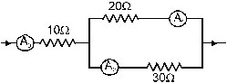
Ans. 1.6 A, 4.0 A.
24. The resistance of the rheostat shown in figure is 30 ohm. Neglecting the meter resistance, find the minimum and maximum currents through the ammeter as the rheostat is varies.
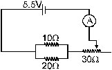
Ans. 0.15 A, 0.83 A
25. Three bulbs, each having a resistance of 180 ohm, are connected in a parallel to an ideal battery of emf 60 V. Find the current delivered by the battery when (a) all the bulbs are switched on, (b) two of the bulbs are switched on and (c) only one bulb is switched on.
26. Suppose you have three resistors of 20 ohm, 50 ohm and 100 ohm. What minimum and maximum resistances can you obtain from these resistors ?
Ans. 12.5 ohm, 170 ohm.
27. A bulb is made using two filaments. A switch selects whether the filaments are used individually or in parallel. When used with a 15 V battery, the bulb can be operated at 5W, 10W or 15W. What should be the resitances of the filaments ?
Ans. 45 ohm , 22.5 ohm
28. Figure shows a part of a circuit. If a current of 12 mA exists in the 5k ohm resistor, find the currents in the other three resistors. What is the potential difference between the points A and B ?
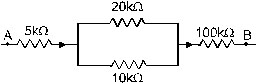
Ans. 4 mA in 20 k ohm resistor, 8 mA in 10 kW resistor and 12 mA in 100 k ohm resistor, 1340 V
29. An ideal battery sends a current of 5A in a resistor. When another resistor of value 10 ohm is connected in parallel, the current through the battery is increased to 6A. Find the resistance of the first resistor.
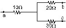
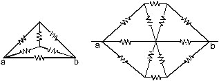
30. Find the equivalent resistance of the network shown in figure between the points a and b.
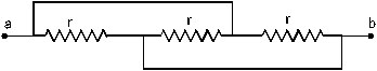
Ans. (a) r/3
31. A wire of rsistance of 15 ohm is bent to form a regular hexagon ABCDEFA. Find the equivalent resistance of the loop between the points (a) A and B, (b) A and C and (c) A and D.
Ans. (a) 2.08 ohm (b) 3.33 ohm (c) 3.75 ohm
32. Consider the circuit shown in figure. Find the current through the 10 ohm resistor when the switch S is (a) open (b) closed.
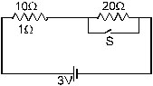
Ans. (a) 0.1 A (b) 0.3 A
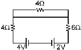
33. Find the currents through the three resistors shown in figure
34. Figure shows a part of an electric circuit. The potentials at the points a, b and c are 30V, 12 V and 2V respectively. Find the currents through the three resistors.
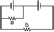
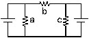
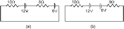
35. Each of the resistors shown in figure has a resistance of 10 W and each of the batteries has an emf of 10 V. Find the currents through the resistors a and b in the two circuits
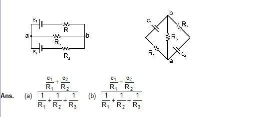
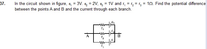
36. Find the potential difference Va – Vb in the circuits shown in figure.
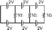
38. Find the current through the 10 ohm resistor shown in figure
Ans. zero
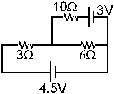
39. Find the current in the three resistors shown in figure
40. What should be the value of R in figure for which the current in it is zero?
41. Find the equivalent resistance of the circuits shown in figure between the points a and b. Each resistor has a resistance r.
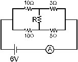
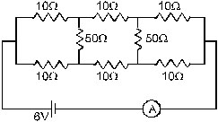
42. Find the current measured by the ammeter in the circuit shown in figure.
43. Consider the circuit shown in figure (a). Find (a) the current in the circuit, (b) the potential drop across the 5 ohm resistor, (c) the potential drop across the 10 ohm resistor, (d) Assume the parts (a),(b) and (c) with reference to figure.
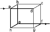
44. Twelve wires, each having equal resistance r, are joined to form a cube as shown in figure. Find the equivalent resistance between the diagonally opposite points a and f.
45. Find the equivalent resistance of the networks shown in figure between the points a and b.
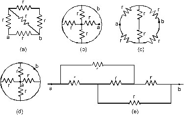
Ans. (a) r (b) r (c) r (d) r (e) r
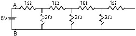
46. An infinite ladder is constructed with 1 ohm and 2 ohm resistors as shown in figure. (a) Find the effective resistance between the points A and B. (b) Find the current that passes through the 2 ohm resistor nearest to the battery.
47. The emf e and the internal resistance r of the battery shown in figure are 4.3 V and 1.0 ohm respectively. The external resistance R is 50 ohm. The resistances of the ammeter and voltmeter are 2.0 ohm and 200 ohm respectively. (a) Find the readings of the two meters. (b) The switch is thrown to the other side. What will be the readings of the two meters now ?
Ans. : (a) 0.1 A, 4.0 V (b) 0.08 A, 4.2 V
48. A voltmeter of resistance 400 W is used to measure the potential difference across the 100 ohm resistor in the circuit shown in figure. (a) What will be the reading of the voltmeter ? (d) What was the potential differences across 100 ohm before the voltmeter was connected ?
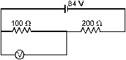
Ans. (a) 24 V (b) 28 V
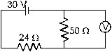
49. The voltmeter shown in figure reads 18 V across the 50 ohm resistor. Find the resistance of the voltmeter.
Ans. 130 ohm
50. A voltmeter consists of a 25 ohm coil connected in series with a 575 ohm resistor. The coil takes 10mA for full scale deflection. What maximum potential difference can be measured on this voltmeter?
Ans. 6 V
51. An ammeter is to be constructed which can read currents upto 2.0 A. If the coil has a resistance of 25W and takes 1mA for full-scale deflection, what should be the resistance of the shunt used?
Ans. 1.25 × 10⁻² ohm.
52. A voltmeter coil has resistance 50.0 ohm and a resistor of 1.15 k ohm is connected in series. It can read potential deference upto 12 volts. If this same coil is used to construct an ammeter which can measure currents upto 2.0 A, what should be the resistance of the shunt used ?
53. The potentiometer wire AB shown in figure is 40 cm long. Where should the free end of the galvanometer be connected on AB so that the galvanometer may show zero deflection ?
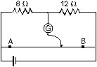
Ans. 16 cm from A.
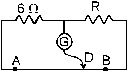
54. The potentiometer wire AB shown in figure is 50 cm long. When AD = 30 cm, no deflection occurs in the galvanometer. Find R.
55. A 6 volt battery of negligible internal resistance is connected across a uniform wire AB of length 100 cm. The positive terminal of another battery of emf 4V and internal resistance 1 ohm is joined to the point A as shown in figure. Take the potential at B to be zero. (a) What are the potentials at the points A and C ? (b) At which point D of the wire AB, the potential is equal to the potential at C. (c) If the point C and D are connected by a wire, what will be the current through it ? (d) If the 4V battery is replaced by 7.5 V battery, what would be the answers of parts (a) and (b) ?
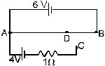
Ans. (a) 6 V, 2 V (b) AD = 66.7 cm (c) zero (d) 6 V, – 1.5 V, –1.5 V, no such point D exists.
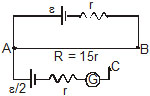
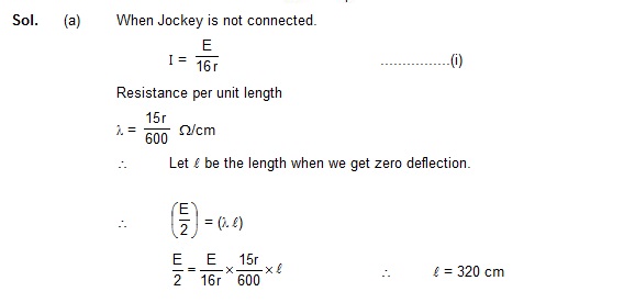
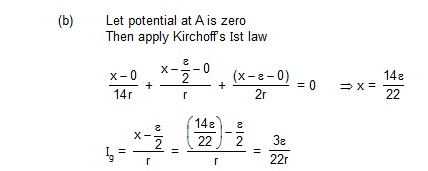
56. Consider the potentiometer circuit arranged as in figure. The potentiometer wire is 600 cm long. (a) At what distance from the point. A should the jockey touch the wire to get zero deflection in the galvanometer ? (b) If the jockey touches the wire at a distance of 560 cm from A, what will be the current in the galvanometer ?
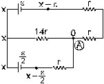
(b) When l = 560 cm
\ r’ = (560) × 15r/600
r’ = 14r
Using KVL in loop
E – I1 .14r – Ir – Ir = 0 ................(i)
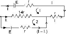
and in loop (2)
– I1 14r + (I – I1)r + E/2 = 0 ...............(ii)
Solving equation (i) and (ii) we have
(30.I1r – E) = (E – 14I1 r)
I1 = 2E/44r
I1 = E/22r and I = 4E/22r
So current in galvanometer
Branch = (I – I1) = 4E/22r - E/22r
Ig = 3E/22r Ans. (a) 320 cm (b) 3e/22r
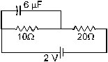
57. Find the charge on the capacitor shown in figure.
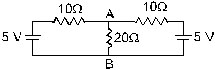
58. (a) Find the current in the 20 ohm resistor shown in figure. (b) If a capacitor of capacitance 4muF is joined between the points A and B, what would be the electrostatic energy stored in it in steady state ?
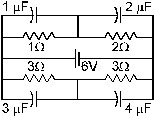
59. Find the charges on the four capacitor of capacitance 1muF, 2muF, 3muF and 4muF shown in figure.
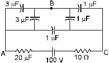
60. Find the potential difference between the points A and B and between the points B and C of figure in steady state.
61. A capacitance C, a resistance R and an emf e are connected in series at t = 0. What is the maximum value of (a) the potential difference across the resistor, (b) the current in the circuit, (c) the the potential difference across the capacitor, (d) the energy stored in the capacitors. (e) the power delivered by the battery and (f) the power converted into heat.
62. A parallel-plate capacitor with plate area 20 cm2 and plate separation 1.0 mm is connected to a battery. The resistance of the circuit is 10 k ohm. Find the time constant of the circuit.
63. A capacitor of capacitance 10 muF is connected to a battery of emf 2V.It is found that it takes 50 ms for the charge on the capacitor to become 12.6 muc. Find the resistance of the circuit.
64. A 20 muF capacitor is joined to a battery of emf 6.0 V through a resistance of 100 ohm. Find the charge on the capacitor 2.0 ms after the connections are made.
65. The plates of a capacitor of capacitance 10 muF, charged to 60 muC, are joined together by a wire of resistance 10 ohm at t = 0. Find the charge on the capacitor in the circuit at (a) t = 0, (b) t = 30 mus, (c) t = 120 mus and (d) t = 1.0 mus.
66. A capacitor of capacitance 8.0 mF is connected to a battery of emf 6.0 V through a resistance of 24 ohm. Find the current in the circuit (a) just after the connections are made and (b) one time constant after the connections are made.
67. A parallel-plate capacitor of plate area 40 cm2 and separation between the plates 0.10 mm is connected to a battery of emf 2.0 V through a 16 ohm resistor. Find the electric field in the capacitor 10 ns after the connecting are made.
68. A parallel-plate capacitor has plate area 20 cm2, plate separation 1.0 mm and a dielectric slab of dielectric constant 5.0 filling up the space between the plates. This capacitor is joined to a battery of emf 6.0 V through a 100 k ohm resistor. Find the energy of the capacitor 8.9 mus after the connections are made.
69. A 100 muF capacitor is joined to a 24 V battery through a 1.0 M ohm resistor. Plot qualitative graphs (a) between current and time for the first 10 minutes and (b) between charge and time for the same period.
70. How many time constants will elapse before the current in a charging RC circuit drops to half of its initial value ? Answer the same question for a discharging RC circuit.
71. How many time constants will elapse before the charge on a capacitor falls to 0.1% of its maximum value in a discharging RC circuit ?
72. How many time constant will elapse before the energy stored in the capacitor reaches half of its equilibrium value in a charging RC circuit ?
73. How many time constants will elapse before the power delivered by the battery drops to half of its maximum value in an RC circuit ?
74. A capacitor of capacitance C is connected to a battery of emf e at t = 0 through a resistancsd R. Find the maximum rate at which energy is stored in the capacitor. When does the rate has this maximum value
75. A capacitor of capacitances 12.0 muF is connected to a battery of emf 6.00 V and internal resistance 1.00 ohm through resistanceless leads. 12.0 mus after the connections are made, what will be (a) the current in the circuit, (b) the power delievered by the battery, (c) the power dissipated in heat and (d) The rate at which energy stored in the capacitor is increasing.
76. A capacitance C charged to a potential difference V is discharged by connecting its plates through a resistance R. Find the heat dissipated in one time constant after the connections are made. Do this by calculating dt at and also by finding the decrease in the energy stored in the capacitor.
77. By evaluating dt, show that when a capacitor is charged by connecting it to a battery through a resistor the energy dissipated as heat equals the energy stored in the capacitor.
78. A parallel-plate capacitor is filled with a dielectric material having resistivity r and dielectric constant K. The capacitor is charged and disconnected from the charging source. The capacitor is slowly discharged through the dielectric. Show that the time constant of the discharge is independent of all geometrical parameters like the plate area or separation between the plates. Find this time constant.
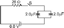
79. Find the charge on each of the capacitors 0.20 ms after the switch S is closed in figure.
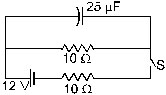
80. The switch S shown in figure is kept closed for a long time and then opened at t = 0. Find the current in the middle 10 ohm resistor at t = 1.0 ms.
81. A capacitor of capacitance 100 muF is connected across a battery of emf 6.0 V through a resistance of 20 k ohm for 4.0 s. The battery is then replaced by a thick wire. What will be the charge on the capacitor 4.0 s after the battery is disconnected ?
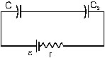
82. Consider the situation shown in figure. The switch is closed at t = 0 when the capacitors are uncharged. Find the charge on the capacitor C1 as a function of time t.
83. A capacitors of capacitance C is given a charge Q. At t = 0, it is connected to an uncharged capacitor of equal capacitance through a resistance R. Find the charge on the capacitor as a function of time.
84. A capacitor of capacitance C is given a charge Q. At t = 0, it is connected to an ideal battery of emf e through a resistance R. Find the charge on the capacitor at time t.