
(a) Definition: Electric charge may be defined as the intrinsic property of certain fundamental particles (electron, proton, etc) due to which they produce electric and magnetic effects.
(B) Charge on a Macrobody: Excess or deficiency of electrons in a body is equal to the charge on a macrobody. A body having excess of electrons in negatively charge and a body having deficiency of electrons is positively charged.
From the study of atomic structure, we know that an atom consists of a central part called nucleus and around the nucleus there are a number of electrons revolving in different paths or orbits. The nucleus contains protons and neutrons. A proton is a positively charged particle while a neutron has no charge. Therefore, the nucleus of an atom bears a positive charge. An electron is a negatively charged particle having negative charge equal to the positive charge on a proton. Normally, the number of electrons is equal to the number of protons in an atom. Therefore, an atom is neutral as a whole; the negative charge on electrons cancelling the positive charge on protons. This leads to the conclusion that under ordinary conditions, a body is neutral i.e. it exhibits no charge.
When this equity or balance is disturbed by removing or supplying electrons, the body acquires a net charge. The body will acquire a positive or negative charge depending upon whether electrons are removed from it or added to it.
(C) Types of Electric Charge: There are two types of charges. They are:
(i) Positive charge: A body having deficiency of electrons.
(ii) Negative charge: A body having excess of electrons.
(D) Charging of a Body: There are a number of methods to charge a body as:
(i) Charging by friction
(ii) Charging by conduction
(iii) Charging by induction etc.
We will discuss charging by friction in detail:
Whenever two bodies (at least one non conductor) are rubbed against each other, heat is produced due to friction present between them. Due to this heat produced, electrons in both the bodies are excited. The body having more electron affinity attracts some of the electrons from other body. Both the bodies develop equal and opposite charges by this method.
(E) Properties of Electric Charge:
(i) Like charges repel and unlike charges attract each other.
(ii) Charge is a scalar quantity.
(iii) Charge is always quantized.
(iv) Charge is conserved.
(v) Charge is always associated with mass.
(F) Unit of Charge: The charge on an electron is so small that it is not convenient to select it the unit of charge. In practice, coulomb is used as the unit of charge, i.e. SI unit of charge is coulomb abbreviated as C. One coulomb of charge is equal to the charge on 625 × 1016 electrons.
1 coulomb = charge on 625 × 1016 electrons or 6.25 × 10¹⁸ electrons
Thus, when we say that a body has a positive charge of one coulomb (i.e + 1C) it means that the body has a deficit of 625 × 1016 electrons from the normal due share.
(A) Static Electricity: A branch of physics which deals with the study of the electric charges at rest and their effects is known as electrostatic or static electricity.
(B) Current Electricity: A branch of physics which deals with the study of the electric charges in motion and their effects is known as current electricity.
(A) Electric Field: Electric field due to a given charge is defined as the space around the charge in which electrostatic force of attraction or repulsion due to charge can be experienced by any other charge. If a test charge experiences no force at a point, the electric field at that point must be zero.
Electric field intensity at any point is the strength of electric field at that point. It is defined as the force experienced by unit positive charge placed at that point.
If F is the force acting on a test charge +q0 at any point r, then electric field intensity at this point is given by
![]()
Electric field is a vector quantity and its S.I. unit is Newton per coulomb or N/C.
(B) Electric Potential: The electric potential at a point in an electric field is defined as the amount of work done in moving a unit +ve charge from infinity to that point, without acceleration or without a change in K.E. against the electric force Mathematically.
![]()
Since work is measured in joule and charge in coulomb, therefore electric potential is measured in joule per coulomb (J/C). This unit occurs so often in our study of electricity, so it has been named as volt, in honour of the scientist Alessandra Volta (the inventor of the voltaic cell).
![]()
Potential is a scalar quantity, therefore it is added algebraically. For a positively charged body potential is positive and for a negatively charged body potential is negative.
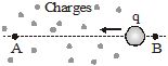
(C) Electric Potential Difference: Consider a charge Q placed at a point P. Let A and B be two other points (B being closer to A) as shown in figure.
![]()
If a charge q is brought from infinity to A, work WA will be done.
The potential at A will then be, ![]()
If charge q is brought from infinity to B, the work done will be WB.
The potential at B will then be, ![]()
The quantity VB – VA is called the potential difference between points A and B in the electric field of charge Q. Mathematically we have,
![]()
Electric potential difference is also measured in volt.
The source of all electricity is charge. As charge is the basis of all electrical phenomena, we need to know the amount of charge on a body. It is measured in coulombs. The coulomb is the SI unit of charge and its symbol is C.
Matter is generally made of protons, electrons and neutrons. Each proton carries a charge of
1.6 × 10⁻¹⁹ coulomb, and each electron carries an equal negative charge. Neutrons do not carry any net charge. Normally, a body has equal number of protons and electrons, and is therefore, electrically neutral. In certain situations, the balance of charges in a body is disturbed.
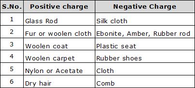
For example:- when a glass rod is rubbed with a silk cloth, some electrons get transferred from the glass rod to the silk. The silk cloth, which gains electrons, becomes negatively charged. And the glass rod, which is left with more protons than electrons, becomes positively charged.
Charged particles or objects can exert forces on each other. While like (similar) charges repel each other, unlike charges attract. Another important thing about charged particles is that they can flow, i.e., they can move in a particular direction. This flow of charged particles is called an electric current. Charged particles such as electrons are present in all substances. But they do not flow on their own. For flow of charges, there has to be a potential difference.
The potential difference between two points A and B is the work done per unit charge in taking a charge from B to A. We express this mathematically as
![]()
Here, V is the potential difference between the points A and B, and VA and VB are the potentials at these points. The potential at infinity is chosen as zero.
If B be the reference point, the potential at B is VB = O. From Equation, the potential at A is
VA = W/q. So, the potential at a point is the work done per unit charge in taking a charge to that point from a chosen reference point. Equation may also be written as
W= qV.
The work done on the charge q is stored as the electric potential energy (U) of the group of charges. So,
U = qV
The unit of potential difference (and potential) is the volt, whose symbol is V. One volt is the potential difference between two points in a current carrying conductor when 1 joule of work is done to move a charge of 1 coulomb from one point to the other.
![]()
The potential difference between two points is sometimes also called the voltage.
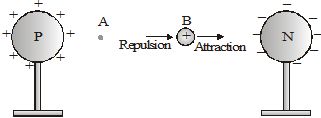
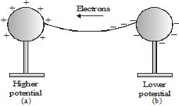
Consider two identical metallic spheres P and N, carrying equal amounts of positive and negative charges respectively. A positive charge is to be taken from B to A. It is attracted by the negatively charged sphere N and repelled by the positively charged sphere P. So, to move the charge towards A, one has to apply a force on it towards the left. Thus, the work done is positive. Hence, the potential difference VA – VB is positive. This means VA > VB'
As one moves towards P, the work done increases; so, the potential increases. And on moving towards N, the potential decreases. So, the potential of P is higher than that of N. In general, the potential of a positively charged body is taken as higher than that of a negatively charged body.
What happens when a free-to-move charge is placed between the spheres? A positive charge will move towards the negatively charged sphere. And a negative charge will move towards the positively charged sphere. That is, a free positive charge moves towards lower potential. And a free negative charge moves towards higher potential.
If the two spheres are connected by a metal wire, electrons from the negatively charged sphere (at a lower potential) will flow to the positively charged sphere (at a higher potential). Eventually, the flow of electrons causes the charges on the spheres to become balanced. When that happens, the spheres no longer carry a net charge, and therefore, have equal potential. So, the flow of electrons stops. So we can say that a potential difference causes charges to flow.
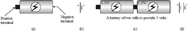
The potential difference provided by things like charged spheres reduces to zero quickly once charges start to flow. So, we have to use cells to provide constant potential difference for a long time. Cells have chemicals inside. Reactions in the cell cause positive and negative charges to gather separately. This creates a potential difference between the terminals of the cell. The terminal at a higher potential is called the positive terminal and the one at a lower potential is called the negative terminal.
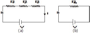
The cells that we commonly use are called dry cells (Figure). In a common dry cell, the small metallic cap at one end is the positive terminal, while the flat metallic plate at the other end is the negative terminal. It provides a potential difference of 1.5 V. A cell is represented by the symbol shown in fig (b). The larger line represents the positive terminal, while the shorter line represents the negative terminal.
Quite often, multiple cells are combined to get a potential difference that is higher than that of a single cell. For example, we connect two 1.5V cells to get a potential difference of 3V (Figure (c)) This is shown using symbols in Figure (d).
Consider a metallic wire ACB connected across a cell of potential difference V. Since the end A is connected to the positive terminal, it is at a higher potential than the end B. In metals, some electrons are loosely bound to the atoms, and can move within it. These are called free electrons. In the metallic wire, these electrons (negative charges) move from the low-potential side B to the high-potential side A. After reaching A, they enter the cell. The chemical reactions in the cell drive these electrons to the negative terminal. From there, they re-enter the wire at the end B. Thus, there is a continuous flow of electrons in the wire from B to C to A. We say that there is an electric current in the wire. In a metal, the flow of negative charges constitutes the current.
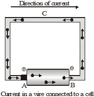
An electric current can also be a flow of positive charges. So, a flow of charge is called an electric current.By convention, the direction of current is taken as the direction of flow of positive charges. Thus, the direction of current is opposite to the direction of flow of negative charges. So, when a wire is connected to a cell, the current in the wire is from the positive-terminal end to the negative-terminal end.
The charge passing per unit time through a given place(area) is the magnitude of the electric current at that place. Thus,
![]()
Here Q is the charge that passes through a place in time t.
Unit of current From Equation, we find that current is charge divided by time. The SI unit of charge is the coulomb and that of time is the second. The SI unit of current, therefore, is coulomb / second. This unit is called the ampere, whose symbol is A.
Thus, if one coulomb of charge passes through a place in one second, the current there is 1 ampere.
Materials that conduct electricity easily are called good conductors or simply, conductors. And, materials that do not conduct electricity easily are called insulators.
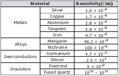
All metals conduct electricity because they have some loosely bound free electrons, which flow when a potential difference is applied. However, some metals conduct electricity better than others. Silver is the best conductor. But because of the high cost of silver, electric wires are made of copper, or in some cases aluminium.
Most nonmetallic solids do not conduct electricity. Although diamond and graphite are both forms of carbon
(a nonmetal), graphite is a conductor while diamond is an insulator. Insulators do not conduct electricity because their electrons are tightly bound to the atoms. Rubber, plastics, wood, glass and porcelain are some examples of insulators. Insulators have many uses. For example, they are used as protective covers on electric wires and electrician's tools.
Certain liquids also conduct electricity. While distilled water is an insulator, addition of certain salts, acids or bases allows it to conduct electricity. Under normal circumstances, gases do not conduct electricity.
A closed path in which a current can flow is called an electric circuit. An electric circuit may have one or more electric elements such as bulbs (or lamps), cells, switches (or plug keys), metal wires, etc. Each element of a circuit has a specific function to play. For example, wires can be used to connect one element to the next. And a plug key or a switch can be used to either complete or break the closed path, thereby starting or stopping the current in the circuit.
Some common circuit elements and their symbols are shown in Figure.
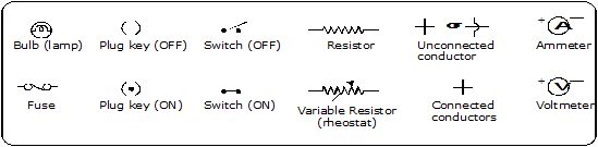
Fig. Some symbols used in circuit diagrams
The electric current in a circuit is measured by an instrument called the ammeter, and the potential difference between two points in it is measured by a voltmeter (in voltage stabilizers). In these meters, a needle moving over a graduated scale gives the value of the measured quantity. Each meter has two terminals. The terminal marked '+' is connected by a wire to the higher-potential side of a circuit, while the terminal marked '–' is connected to the lower-potential side.
To measure the current through an element of a circuit, an ammeter is connected in such a way that the current flowing through it also flows through the element. Such a connection is called a series connection. In Figure, the current i flowing through the lamp also flows through the ammeter. The reading of the ammeter gives the current through the lamp. Note that if the ammeter is removed, there will be a gap, and the current through the circuit will stop.
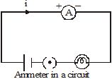
Two or more electric elements are said to be connected in series if the current flowing through one also flows through the rest.
An ammeter is always connected in series in a circuit.
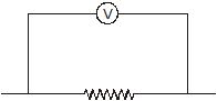
Figure shows a circuit that has two lamps connected to a cell. We want to measure the potential difference across the lamp L2, i.e., between the points A and B. As A is on the side of the positive terminal of the cell, its potential is higher than that of B. So, the '+' terminal of the voltmeter is connected to A, and the '–' terminal, to B. The reading of the voltmeter gives the potential difference across L2. The current flowing through the voltmeter is different from those flowing through the other elements of the circuit. Also, even if the voltmeter is removed, the current continues to flow in the circuit. Note that the potential difference across L2 and the voltmeter is the same. Such a connection is called a parallel connection.
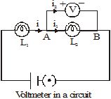
Two or more electric elements are said to be connected in parallel if the same potential difference exists across them.
The electric current through a metallic element or wire is directly proportional to the potential difference applied between its ends, provided the temperature remains constant.
If a potential difference V is applied to an element and a current i passes through it,
i µ V
or ![]()
Thus Ohm's Law V = iR
![]()
Here R is a constant for the given element (metallic wire) at a given temperature and is called its resistance. It is the property of a conductor to resist the flow of charges through it.
From equation, ![]()
So, for a given potential difference,
Thus, for a given potential difference, the current is inversely proportional to the resistance. The higher is the resistance, the lower is the current. If the resistance is doubled, the current is halved. Good conductors have low resistance, while insulators have very high resistance.
Potential difference is measured in volts, and current is measured in amperes. From Equation, R = V/i. So, the unit of resistance is volt/ampere. This unit is called the ohm, and its symbol is W. We can define one ohm as follows.
If a potential difference of 1 volt is applied across an element, and a current of 1 ampere passes through it, the resistance of the element is called 1 ohm.
The resistance of the conductor depends on:
(i) on its length
(ii) on its area of cross-section
(iii) on the nature of its material
(iv) Resistance depends on temperature (resistance increases with increase in temperature)
Resistance of a uniform metallic conductor is directly proportional to its length (l) and inversely proportional to the area of cross-section (A).
Combining eqs. we get or
Where r (rho) is a constant of proportionality and is called electrical resistivity of the material of the conductor.
Here, r is a constant for a given material at a given temperature. It is called the resistivity of the material. the resistivity of a material is the resistance per unit length of a unit cross section of the material. The SI unit of a material depends on its temperature. For metals and alloys of metals, the resistivity increases with rise in temperature. The SI unit of resistivity is W m.
SERIES AND PARALLEL CONNECTIONS OF RESISTORS
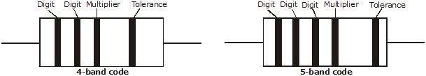
A conducting material (e.g., a wire) of a particular resistance meant for use in a circuit is called a resistor. A resistor is sometimes simply referred to as a resistance. It is represented by the symbol . Two or more resistors can be connected in series, in parallel or in a manner that is a combination of these two.
Two or more resistors are said to be connected in series if the current flowing through one also flows through the rest.
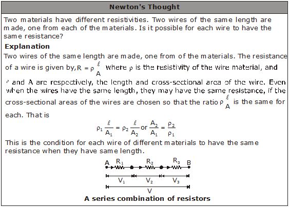
The total potential difference across the combination of resistors connected in series is equal to the sum of the potential differences across the individual resistors.
![]()
Figure (a) shows three resistors of resistances R1, R2 and R3 connected in series. The cell connected across the combination maintains a potential difference V across the combination. The current through the cell is i. The same current i flows through each resistor.
Let us replace the combination of resistors by a single resistor Req such that the current does not change, i.e., it remains i. This resistance is called the equivalent resistance of the combination, and its value is given by Ohm's law as Req = V/i
Thus V = iReq.
The potential differences V1 , V2 and V3 across the resistors R1 , R2 and R3 respectively are given by
Ohm's law as : V1 = iR1 , V2 = iR2 , V3 = iR3
Since the resistors are in series, V = V1 + V2 + V3
Substituting the values of the potential differences in the above equation,
iReq = iR1 + iR2 + iR3
or iReq =i(R1 +R2 +R3)
or
Similarly, for n resistors connected in series,
Equivalent resistance of resistors in series : ![]()
The total current flowing into the combination is equal to the sum of the currents passing through the individual resistors.
![]()
If resistors are connected in such a way that the same potential difference gets applied to each of them, they are said to be connected in parallel.
Figure (a) shows three resistors of resistances R1, R2 and R3 connected in parallel across the points A and B. The cell connected across these two points maintains a potential difference V across each resistor. The current through the cell is i. It gets divided at A into three parts i1, i2 and i3, which flow through R1, R2 and R3 respectively.
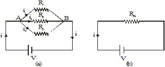
Let us replace the combination of resistors by an equivalent resistor Req such that the current i in the circuit does not change (Fig). The equivalent resistance is given by Ohm's law as Req = V/i.
Thus,
![]()
The currents i1 , i2 and i3 through the resistors R1, R2 and R3 respectively are given by Ohm's law as
![]()
Since the resistors are in parallel,
i = i1 + i2 + i3
Substituting the values of the currents in the above equation,
![]()
or
![]()
Similarly, if there are n resistors connected in parallel, their equivalent resistance Req is given by
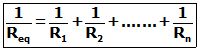
For two resistances R1 and R2 connected in parallel,
![]()
or
![]()
The equivalent resistance in a parallel connection is less than each of the resistances.
When a resistance is joined parallel to a comparatively smaller resistance, the equivalent resistance is very close to the value of the smaller resistance.
Note : If a resistor connected in series with others is removed or fails, the current through each resistor becomes zero. On the other hand, if a resistor connected in parallel with others fails or is removed, the current continues to flow through the other resistors.
Consider the circuit in fig. The resistors R1 and R2 are connected in parallel. The current i gets distributed in the two resistors.
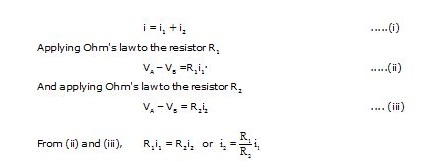
Substituting for i2 in (i), we have
Similarly, 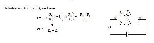
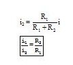
Thus,
The current through each branch in a parallel combination of resistors is inversely proportional to its resistance.
You must have seen tiny bulbs strung together for decorating buildings during festivals like Diwali, and occasions like marriages, etc. These bulbs are connected in series, and the mains voltage is applied to the combination. The potential difference (V) of the mains gets divided across the bulbs (V = V1 + V2 + V3 + ... ). So, a small potential difference exists across each bulb, close to that required to make the bulb work. However, the same current flows through all the bulbs. So, if one bulb goes bad, the current through it stops, and this stops the current through the rest of the bulbs as well. To make the chain of lights work, we have to find and replace the defective bulb. This problem does not occur with the lights in our house. That is because in houses, lights, fans, etc., are connected in parallel. In parallel connection, the same mains voltage gets applied to each device, but the current through each is different. If one of them goes bad, the current in the other branches of the parallel connection does not stop. Another advantage of parallel connection is that, unlike series connection, each device can draw a different current, as per its requirement.
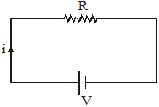
When an electric current passes through a bulb, the filament gets so hot that it glows and emits light. When a current passes through the filament of an electric iron, the iron becomes very hot. This increase in temperature is due to what is called 'the heat produced due to current'.Suppose a resistor R is connected to a cell. The cell maintains a potential difference V across the resistor, driving a current i through it.
So, V = iR ......(i)
The current through the resistor is actually a flow of negative charges (electrons). Inside the cell, the negative charges flow from the positive to the negative terminal. The cell does work = QV to take a charge through the potential difference V between its terminals. This increases the energy of the charge by QV. This increased energy gets converted to heat in the resistor. So, the energy appearing as heat is given by
U = QV ......(ii)
The charge that passes through the wire in time t is
Q =it. ......(iii)
Using (i), (ii) and (iii), we find that the heat produced in the wire in time t is
U =QV = (it) (iR) =i2 Rt.
From Equation the heat produced is proportional to the square of the current, if R and t remain constant. So, if the current passing for a given time through a given resistance is doubled, the heat produced becomes four times. Similarly, for a given i and t, the heat produced is proportional to R. If the same current i passes through two resistances in a given time, more heat will be produced in the larger resistance. The heat produced can also be written as.
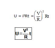
For a given V and t, the heat produced is inversely proportional to R. So, if the same potential difference is applied across two resistances, more heat will be produced in the smaller resistance.
We have seen above that the increased energy of a charge gets converted to heat in the resistor. The increase in energy comes from the work done by the cell. This uses up the chemical energy of the cell. So, the energy appearing as heat in the resistor ultimately comes at the expense of the chemical energy of the cell.
Not always is the work done by a cell converted to heat. Immediately after a motor is connected to a cell, the speed of the shaft of the motor increases. A part of the work done by the cell goes into producing the increase in kinetic energy. And a part is used to overcome friction, etc. When the motor achieves a constant speed, its kinetic energy does not change. So the work done by the cell is only used to overcome friction, etc. This appears as heat. That is why the cover over a motor becomes warm on use.
The heating effect of electric current has many uses. Electric bulbs, room heaters, electric irons, immersion heaters, toasters, electric fuses and a number of other appliances work on this principle. In all of these, a wire of suitable resistance, commonly called the heating element, is connected to the power supply. The current passing through the element produces heat in it, which is used for some specific purpose.
(i) Electric bulb: An electric bulb has a simple structure. It consists of a sealed glass bulb that has a tungsten filament connected to two electrical contacts. The bulb is filled with an unreactive gas like argon or nitrogen. To produce white light, the filament has to be heated to about 3000°C by passing a current through it. Obviously, the material of the filament should such that it does not melt at this temperature. Tungsten is used for the filament because its melting point is about 3400°C. The sealed glass bulb serves two purposes. First, it protects the filament from oxidation and the effects of humidity. Secondly, the small enclosed volume makes it easier to maintain the required temperature, as without it the loss of heat would be more.
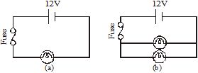
(ii) Fuse: A fuse is a safety device that does not allow excessive current to flow through an electric circuit. It consists of a metallic wire of low melting point, fixed between the two terminals of a fuse plug. The fuse plug fits into a fuse socket connected in the circuit. Fuses are available in various shapes. The fuse plug is used in household wiring. It is made of porcelain.
A fuse is connected in series with an appliance (such as a TV) or a group of appliances (such as the lights and fans in a room). So, the current through the fuse is the same as the current through the appliance or the group of appliances. If this current exceeds a safe value, the heat produced in the fuse wire causes it to melt immediately. This breaks the circuit, preventing any damage. Figure shows examples of how a fuse is connected in circuits.
Good-quality fuse wires are made of tin, as it has a low melting point. Some fuse wires are made of an alloy of tin and copper. The thickness of the fuse wire depends on the circuit in which it is to be used. If a section of the circuit is meant to carry a maximum of 5A current, the fuse wire should also be able to carry currents up to 5A. Similarly, for wiring meant for 15A, the fuse wire should be thicker, and should be able to carry currents up to 15A.
A current always produces some heat, whether we use the heat or not. If the heat produced cannot be utilized, it represents a wastage of energy. A considerable amount of energy is thus wasted in the transmission of electricity from the generating station to our homes. Sometimes, the heat produced in a device is so much that it can damage the device, unless proper cooling arrangements are made. To dissipate the heat produced in TV sets, monitors, etc., their cabinets have grills for air to pass. Certain components of a computer get so hot that they have fans to cool them.
Power is the rate of doing work, or the rate at which energy is produced or consumed. The electrical energy produced or consumed per unit time is called electric power. In an electric circuit, the power is
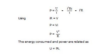
The SI unit of energy is the joule, and that of time is the second. The SI unit of power is therefore joule/second. This unit is called the watt, whose symbol is W.
Take an electric bulb and see what is written on it. Apart from the name and the symbol of the company, we will find values of power and potential difference. For example, it could be 60W, 220V. It means that 220V should be applied across this bulb, and when 220V is applied, the power consumed will be 60W. We will find similar markings on all electric· appliances. For an electric appliance, the values of power and voltage taken together form what is called the rating of the appliance.
Þ From the rating of an appliance, you can easily calculate its resistance by using the equation P = . Note that higher the power rating, smaller the resistance. So, a 1000W heater has less resistance than a 100W bulb. We can also calculate the current drawn by an appliance by using the relation i = .
Power is the rate of energy consumed or produced. If 1 joule of energy is used per second, the energy is used at the rate of 1 watt. In other words, if energy is used at the rate of 1 watt, the total energy used in 1 second is 1 joule. How much energy is used in 1 hour if it is used at the rate of 1000 watt?
It is (1000 watt) × (3600 second) = 3,600,000 joule.
This amount of energy is called 1 kilowatt hour, written in short as kWh.
Thus, 1 kWh =3,600,000 J = 3.6 × 10⁶ J.
The electrical energy used in houses, factories, etc., is measured in kilowatt hours. The cost of electricity is fixed per kilowatt hour. One kilowatt hour of electrical energy is called one unit.
(A) Earthing: Earthing means to connect the metal case of electrical appliance to the earth (at zero potential) by means of a metal wire called "earth wire". In household circuits, we have three wires, the live wire, the neutral wire and the earth wire. One end of the earth wire is buried in the earth. We connect the earth wire to the metal case of the electrical appliance by using a three-pinplug.
The metal casing of the appliance will now always remain at the zero potential of the earth. We say that the appliance has been earthed or grounded. If, by chance, the live wire touches the metal case of the electric iron (or any other appliance) which has been earthed, then the current passed directly to the earth through the earth wire. It does not need our body to pass the current and therefore, we do not get an electric shock. Actually, a very heavy current flows through the earth wire and the fuse of house-hold wiring blows out or melts. And it cuts off the power supply. In this way, earthing also saves the electrical appliance from damage due to excessive current.
(B) Miniature Circuit Breaker: These days a device called a miniature circuit breaker (MCB) is also used instead of or in addition of fuses, in the household electric circuits. It is a switch that automatically switches off a circuit if the current in it exceeds the specified maximum limit.
An electric appliance is provided with a three-core flexible cable. The insulation on the three wires is of different colours. The old convention is red for live, black for neutral and green for earth. The new international convention is brown for live, light blue for neutral and green (or yellow) for earth.
A galvanometer is an instrument that can detect the presence of a current in a circuit. The pointer remains at zero (the centre of the scale) for zero current flowing through it. It can deflect either to the left or to the right of the zero mark depending on the direction of current.
Galvanometers are of two types:
(i) Moving coil galvanometer (ii) Moving magnet galvanometer
It is used to make ammeter and voltmeter as follows:
(A) Ammeter: Ammeter is an electrical instrument which measures the strength of current in 'ampere' in a circuitry which is always connected in series in circuit so that total current (to be measured) may pass through it. The resistance of an ideal ammeter is zero (practically it should be minimum).
(B) Voltmeter: It is an electrical instrument which measures the potential difference in 'volt' between two points of electric circuit. The only difference between ammeter and voltmeter is that ammeter has its negligible (approximately zero) resistance so that it may measure current of circuit passing through it more accurately giving the deflection accordingly, while the voltmeter passes negligible current through itself so that potential difference developed due to maximum current passing through circuit may be measured.
Voltmeter has very high resistance and the resistance of an ideal voltmeter is infinite.
A voltmeter is always connected in parallel.
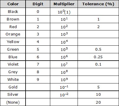
Note: Short trick for colors:- B B Roy of Great Britain has very good Wife.
Ex.1 A piece of wire of resistance R is cut into five equal parts. These parts are then connected in parallel. If the equivalent resistance of this combination is R', then the ratio R/R' is :
(A) 1/25 (B) 1/5 (C) 5 (D) 25
Sol. Resistance of each one of the five parts =
Resistance of five parts connected in parallel is given by
or or 25
Thus, (D) is the correct answer.
Ex.2 Which of the following terms does not represent electrical power in a circuit :
(A) I2R (B) IR2 (C) VI (D) V2/R
Sol. Electrical power, P = VI = (IR) I = I2R = V
Obviously, IR2 does not represent electrical power in a circuit.
Thus, (B) is the correct answer.
Ex.3 An electric bulb is rated 220 V and 100 W. When it is operated on 110 V, the power consumed will be:
(A) 100 W (B) 75 W (C) 50 W (D) 25 W
Sol. Resistance of the electric bulbs, R = (P = V2/R)
or R = = 484W
Power consumed by the bulb when it is operated at 110 V is given by
P' = (V' = 100 V)
Thus, (D) is the correct answer.
Ex.4 Two conducting wires of the same material and of equal lengths and equal diameters are first connected in series and then in parallel in an electric circuit. The ratio of the heat produced in series and parallel combinations would be :
(A) 1:2 (B) 2:1 (C) 1:4 (D) 4:1
Sol. Since both the wires are made of the same material and have equal lengths and equal diameters, these have the same resistance. Let it be R.
When connected in series, their equivalent resistance is given by
Rs = R + R = 2R
When connected in parallel, their equivalent resistance is given by
or Rp =
Further, electrical power is given by P =
Power (or heat produced) in series, Ps =
Power (or heat produced) in parallel, Pp =
Thus,
or Ps : Pp : : 1 : 4
Thus, (C) is the correct answer.
Ex.5 How is voltmeter connected in the circuit to measure potential difference between two points?
Sol. A voltmeter is always connected in parallel across the points between which the p.d. is to be determined.
Ex.6 A copper wire has a diameter of 0.5 mm and a resistivity of 1.6 × 10⁻⁶ ohm cm. How much of this wire would be required to make a 10 ohm coil? How much does the resistance change if the diameter is doubled?
Sol. 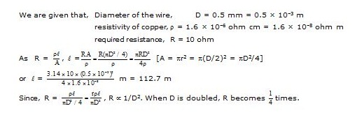
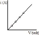
Ex.7 The values of current, I, flowing in a given resistor for the corresponding values of potential difference, V, across the resistor are given below :
I (ampere) : 0.5 1.0 2.0 3.0 4.0
V (volt) : 1.6 3.4 6.7 10.2 13.2
Plot a graph between V and I and calculate the resistance of the resistor.
Sol. The V-I graph is as shown in fig.
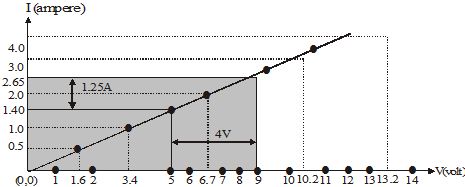
For V = 4V (i.e., 9V – 5V), I = 1.25 A (i.e., 2.65 A – 1.40 A). Therefore, R = = 3.2 W
The value of R obtained from the graph depends upon the accuracy with which the graph is plotted.
Ex.8 When a 12 V battery is connected across an unknown resistor, there is a current of 2.5 mA in the circuit. Find the value of the resistance of the resistor.
Sol. 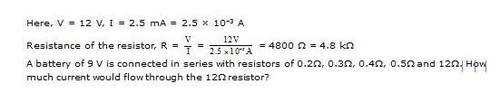
Ex.9 A battery of 9 V is connected in series with resistors of 0.2W, 0.3W, 0.4W, 0.5W and 12W. How much current would flow through the 12W resistor?
Sol. Since all the resistors are in seies, equivalent resistance,
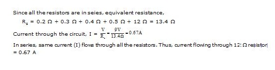
Ex.10 How many 176W resistors (in parallel) are required to carry 5 A in 220 V line?
Sol. Here, I = 5A, V = 220 V.
Resistance required in the circuit, R = , Resistance of each resistor, r = 176 W
If n resistors, each of resistance r, are connected in parallel to get the required resistance R, then R =
or 44 = or n = = 4
Ex.11 Show how you would connect three resistors, each of resistance 6W, so that the combination has a resistance of (i) 9W (ii) 2W.
Sol. (i) In order to get a resistance of 9 W from three resistors, each of resistance 6 W, we connect two resistors in parallel and this parallel combination (or resistance 3W) in series with the third resistor as shown in fig.
(ii) In order to get a resistance of 2W from three resistors, each of resistance 6 W, we connect all the three resistors in parallel as shown in fig (b) as equivalent resistance in parallel combination, i.e., Rp is given by Rp = = 2W.
Ex.12 Several electric bulbs designed to be used on a 220 V electric supply line, are rated 10 W. How many lamps can be connected in parallel with each other across the two wires of 220 V line if the maximum allowable current is 5 A?
Sol. Resistance of each bulb, r =
Total resistance in the circuit, R
Let n be the number of bulb (each of resistance r) to be connected in parallel to obtain a resistance R.
Clearly, R = or n =
Ex.13 A hot plate of an electric oven connected to a 220 V line has two resistance coils A and B, each of 24W resistance, which may be used separately, in series, or in parallel. What are the currents in the three cases?
Sol. Here, potential difference, V = 220 V
Resistance of each coil, r = 24 W
(i) When each of the coils A or B is connected separately, current through each foil, i.e.,
I =
(ii) When coils A and B are connected in series, equivalent resistance in the circuit,
Rs = r + r = 2r = 48W
Current through the series combination, ie.e, Is =
(iii) When the coils A and B are connected in parallel, equivalent resistance in the circuit,
Rp =
Current through the parallel combination, ie.e, Ip =
Ex.14 Compare the power used in the 2W resistor in each of the following circuits :
(i) a 6 V battery in series with 1W and 2W resistors, and
(ii) a 4 V battery in parallel with 12W and 2W resistors.
Sol. 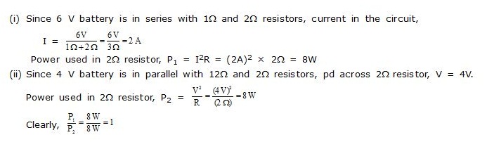
Ex.15 Two lamps, one rated 100 W at 220 V, and the other 60 W at 220 V, are connected in parallel to the electric mains supply. What current is drawn from the line if the supply voltage is 220 V?
Sol. 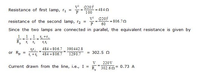
Ex.16 Which uses more energy, a 250 W TV set in 1 h, or a 1200 W toaster in 10 minutes?
Sol. Energy used by 250 W TV set in 1 h = 250 W × 1h = 250 Wh
Energy used by 1200 W toaster in 10 min. (i.e., 1/6 h) = 1200 W × (1/6) h = 200 Wh
Thus, a 250 W TV set uses more power in 1 h than a 1200 W toaster in 10 minutes.
Ex.17 An electric heater of resistance 8W draws 15 A from the service mains for 2 hour. Calculate the rate at which heat is developed in the heater.
Sol. Here, I = 15A, R = 8 W, t = 2h
Rate at which heat is developed, i.e, electric power, P = I2 R = (15)2 × 8 = 1800 W = 1800 J/s
Ex.18 Explain the following :
(a) Why is tungsten used almost exclusively for filament of incandescent lamps?
(b) Why are the conductors of electric heating devices, such as toasters and electric irons, made of an alloy rather than a pure metal?
(c) Why is the series arrangement not used for domestic circuits?
(d) How does the resistance of a wire vary with its cross-sectional area?
(e) Why are copper and aluminium wires usually employed for electricity transmission.
Sol. (a) Tungsten has a high melting point (3380°C) and becomes incandescent (i.e., emits light at a high temperature) at 2400 K.
(b) The resistivity of an alloy is generally higher than that of pure metals of which it is made of.
(c) In series arrangement, if any one of the appliances fails or is switched off, all the other appliances stop working because the same current is passing through all the appliances.
(d) The resistance of a wire (R) varies inversely as its cross-sectional area (A) as R µ 1/A.
(e) Copper and Aluminium wires possess low resistivity and as such are generally used for electricity transmission.
Q.1 What does an electric circuit mean ?
Ans. An electric circuit is a closed and continuous path consisting of many devices like resistors, electric bulbs, etc. through which an electric current flows.
Q.2 Define the unit of current.
Ans. The 51 unit of current is ampere (A). Current flowing through a conductor Is said to be 1 ampere if 1 coulomb of charge flows through it in 1 second.
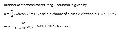
Q.3 Calculate the number of electrons constituting one coulomb of charge.
Ans.
Q.4 Name a device that helps to maintain a potential difference across a conductor.
Ans. A battery can be used to maintain a potential difference across a conductor.
Q.5 What is meant by saying that the potential difference between two points is 1 V ?
Ans. Potential difference between two points is 1 volt if 1 joule of work is done to carry a charge of 1 coulomb from one point to the other.
Q.6 How much energy is given to each coulomb of charge passing through a 6V battery?
Ans. Work done, W = QV Where, Q = 1C; V = 6V W = 1C × 6V = 6J
Q.7 On what factors does the resistance of a conductor depend?
Ans. The resistance (R) of a conductor depends upon
(i) its length (l): R µ l
(ii) its cross-sectional area (A): R µ
(iii) Nature of material i.e., resistivity (r) of its material: R µ r
(iv) Temperature: more the temperature, more will be its resistance.
Q.8 Does current flow more easily through a thick wire or a thin wire of the same material when connected to the same source? Why?
Ans. The current flows more easily through a thick wire than through a thin wire. This is because the resistance R of a thick wire (large area of cross-section) is less than that of a thin wire (small area of cross-section) as R µ .
Q.9 Let the resistance of an electrical component remains constant while the potential difference across the two ends of the component decreases to half its former value. What change will occur in the current through it?
Ans. We know that I = V/R, when potential difference becomes V/2, and resistance remains constant, then, current becomes 1/2 of its former value.
Q.10 Why are coils of electric toasters and electric irons made of an alloy rather than a pure metal?
Ans. This is because (i) resistivity of an alloy is generally higher than that of pure metals (ii) an alloy has a high melting point and it does not oxidise at high temperatures.
Q.11 (a) which among iron and mercury is a better conductor? Given, riron = 10.0 × 10⁻⁸ Wm and rmercury =
94.0 × 10⁻⁸ Wm.
(b) Which material is the best conductor?
Ans. (a) Iron is a better conductor than mercury as resistivity (r) for iron is less than that for mercury.
(b) Silver is the best conductor because its resistivity (r) is least.
Q.12 Draw a schematic diagram of a circuit consisting of a battery of three cells of 2V each, a 5 ohm resistor, an 8 ohm resistor, and a 12 ohm resistor, and a plug key, all connected in series.
Ans. 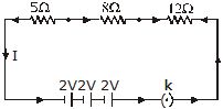
Q.13 Redraw the circuit of Q. 12, putting in an ammeter to measure,the current through the resistors and a voltmeter to measure the voltage across the 12 ohm resistor. What would be the reading in the ammeter and the voltmeter?
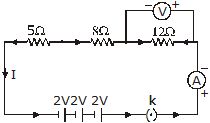
Ans. Since all the three resistances are in series, total resistance in the circuit,
R = 5 + 8 + 12 = 25W
Current in the circuit, , thus, ammeter will read 0.24 A.
Potential difference across 12 ohm resistor, V = I × R = 0.24 × 12 = 2.88 V
Q.14 Judge the equivalent resistance when the following are connected in parallel (a) 1W and 106W (b) 1W, 103W and 106W.
Ans. (a) Approx. 1 W(slightly less than 1W) as other one (106W) is very large as compared to 1W. In parallel combination of resistors, the equivalent resistance is lesser than the least resistance (in this case, 1W).
(b) Again, resistance is approx. 1W(slightly less than 1W).
Q.15 An electric lamp of 100W, a toaster of resistance 50W and a water filter of resistance 500W are connected in parallel to a 220V source. What is the resistance of an electric iron connected to the same source that takes as much current as in three appliances and what is current through it?
Ans. Resistance of the electric lamp, R1 = 100 W; resistance of toaster, R2 = 50W; resistance of water filter, R3 = 500W
Since R1, R2 and R3 are connected in Parallel, their equivalent resistance (Rp) is given by
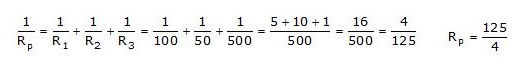
Current through the three appliances, i.e.,
Q.16 What are the advantages of connecting electrical devices in parallel with the battery instead of connecting them in series.
Ans. (a) In case of devices in parallel. if one device gets damaged (or open), all other will work as usual as the whole circuit does not break. This is not with the devices connected in series because when one device fails, the circuit breaks and all devices stop working.
(b) Since potential difference across all devices is same in parallel Circuit, they will draw required current according to their resistances. This is not so in series circuit where same current flows through all the devices, irrespective of their resistances.
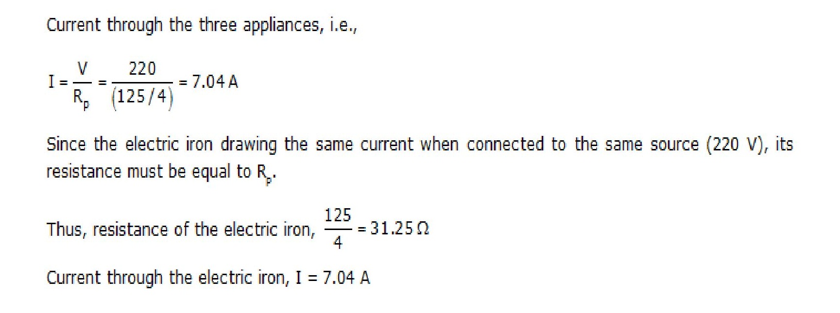
Q.17 How can three resistors of resistances 2W, 3W and 6W be connected to give a total resistance of (a) 4W (b) 1W ?
Ans. (a) The get a total resistance of 4W from resistors of resistance 2W, 3W and 6W, the resistors are joined as shown below.
The resistors having resistances 3W and 6W are connected in parallel. This combination is connected in series with the resistor of resistance 2W. Let us check it mathematically, equivalent resistance of 3W and 6W resistors is,
Now, R1 and 2W resistors are in series, their equivalent resistance is Re = R1 + 2 = 2 + 2 = 4W.
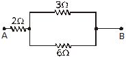
(b) To get a resistance of 1W from three given resistors of resistance 2W, 3W, 6W, are joined as shown below.
They all are connected in parallel. Their equivalent resistance is given by,
R = W
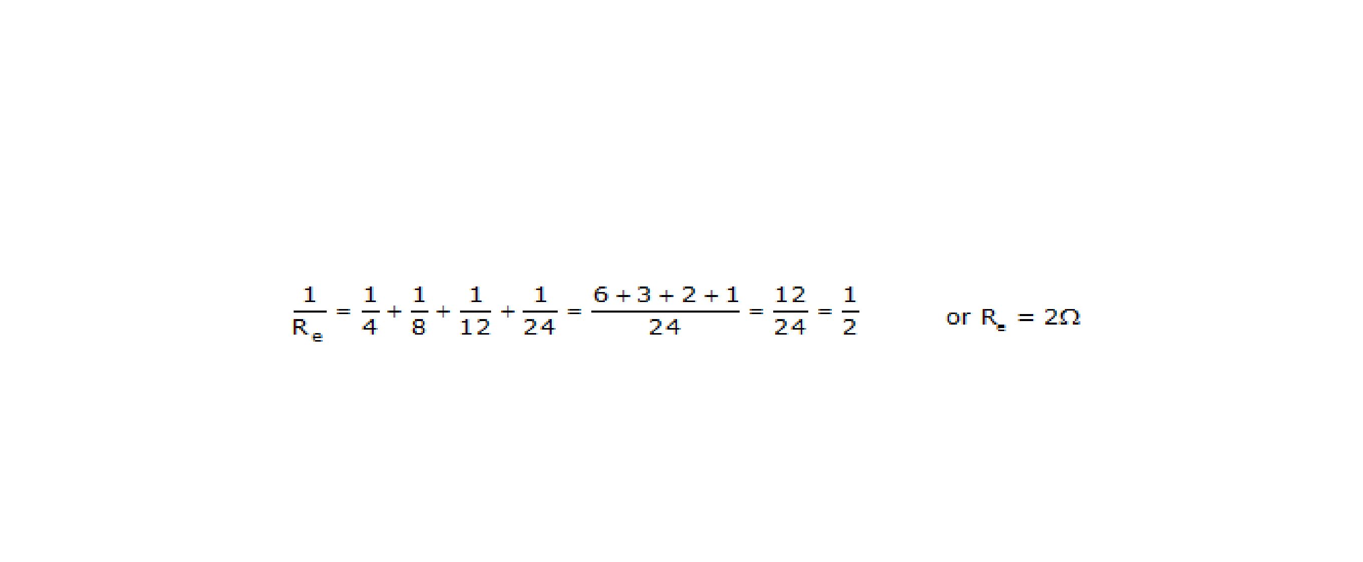
Q.18 What is (a) the highest, (b) the lowest total resistance that can be secured by combinations of four coils of resistance 4W, 8W, 12W, 24W?
Ans. (a) The highest resistance is secured when all the resistors are connected in series. The equivalent resistance is given by,
Re = 4W + 8W + 12W + 24W = 48W.
(b) The lowest resistance is secured when all the four coils are connected in parallel. The equivalent resistance is given by,
Q.19 Why does the cord of electric heater not glow while the heating element does?
Ans. The cord of an electric heater is made of thick copper wire and has much lower resistance than the heating element. For the same current (I) flowing through the cord and the element, heat produced in the element is much more than that produced in the cord. As a result, the element becomes very hot and glows whereas the cord does not become hot and as such does not glow.
Q.20 Compute the heat generated while transferring 96000 coulombs of charge in one hour through a potential difference of 50 V.
Ans. Here, charge, Q = 96000C; time, t = 1 hr
potential difference, V = 50V.
Heat produced, H = V I t = V × q [q = I t]
= 96000C × 50V = 4.8 × 10⁶ J.
Q.21 An electric iron of resistance 20W takes a current of 5A. Calculate the heat developed in 30s.
Ans. Here, resistance, R = 20W, current, I = 5A, time, t = 30 s.
Heat produced, H = I2 R t = (5)2 5 20 × 30 = 1.5 × 10⁴ J.
Q.22 What determines the rate at which energy is delivered by a current?
Ans. Electric power determines the rate at which energy is delivered by a current.
Q.23 An electric motor takes 5A from a 220V. Determine the power and energy consumed in 2Hr.
Ans. Here, current, I = 5A; potential difference, V = 220V; time, t = 2hr = 2 × 60 × 60 = 72000
= 7.92 × 10⁶ J
Q.1 Define resistivity of a material. [2004]
Q.2 A cylinder of a material is 10 cm long and has a cross-section of 2 cm2. If its resistance along the length be 20W, what will be its resistivity in number and units. [2004]
Q.3 Why is tungsten metal selected for making filaments of incandescent lamps ? [2005]
Q.4 A resistance of 10 ohm is bent in the form of a closed circle. What is the effective resistance between the two points at the ends of any diameter of this circle? [2005]
Q.5 A wire of resistance 5W is bent in the form of a closed circle. What is the resistance between two points at the ends of any diameter of the circle ? [2005]
Q.6 A wire of resistance 20W is bent in the form of a closed circle. What is the effective resistance between the two points at the ends of any diameter of the circle? [2005]
Q.7 Why is much less heat generated in long electric cables than in filaments of electric bulbs? [2005]
Q.8 State which has a higher resistance: a 50 W or a 25 W lamp bulb and how many times? [2005]
Q.9 What is the power of torch bulb rated at 2·5 V and 500 mA ? [2005]
Q.10 There are two electric bulbs, (i) marked 60 W, 220 V and (ii) marked 100 W ; 220 V. Which one of them has higher resistance ? [2006]
Q.11 Out of the two, a toaster of 1 kW and an electric heater of 2 kW, which has a greater resistance? [2006]
Q.12 What is the SI unit of electrical potential ? [2007]
Q.13 What is meant by the statement "Potential difference between two points A and B in an electric circuit is 1 volt ? [2007]
Q.14 Why is series arrangement not used for connecting domestic electrical appliances in a circuit ? [2008]
Q.15 Out of 60 W and 40 W lamps, which one has a higher resistance when in use? [2008]
Q.16 An electric bulb draws a current of 0·2 A when the voltage is 220 volts. Calculate the amount of charge flowing through it in one hour. [2004]
Q.17 An electric iron draws a current of 0·5 A when the voltage is 200 volts. Calculate the amount of electric charge flowing through it in one hour. [2004]
Q.18 An electric appliance draws a current of 0·4 A when the voltage is 200 volts. Calculate the amount of charge flowing through it in one hour. [2004]
Q.19 Calculate the amount of charge that would flow in 1 hour through the element of an electric bulb drawing a current of 0·2 A. [2004]
Q.20 Calculate the amount of charge that would flow in 2 hours through the element of an electric bulb drawing a current of 0·25 A. [2004]
Q.21 Calculate the amount of charge that would flow in 1 hour through the element of an electric iron drawing a current of 0·4 A. [2004]
Q.22 Derive the relation R = R1 + R2 + R3 when resistors are joined in series. [2005]
Q.23 (i) Draw a circuit diagram to show how two resistors are connected in series. [2006]
(ii) In a circuit if the two resistors of 5 W and 10 W are connected in series, how does the current passing through the two resistors compare ?
Q.24 A bulb is rated at 5.0 V, 100 mA. Calculate its (i) power and (ii) resistance. [2006]
Q.25 An electric iron has a rating of 750 W, 220 V. Calculate [2007]
(i) current passing through it, and
(ii) its resistance, when in use.
Q.26 An electric lamp is marked 100 W, 220 V. It is used for 5 hours daily. Calculate [2007]
(i) its resistance while glowing (ii) energy consumed in kWh per day.
Q.27 Three resistors are connected as shown in Fig. Through a resistor of 5 ohm, a current of 1 ampere is flowing. [2003]
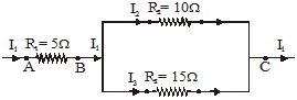
(a) What is the potential difference across AB and across AC ?
(b) What is the current through the other two resistors ?
(c) What is the total resistance?
Q.28 An electric bulb is rated at 200 V-100 W. What is its resistance? Five such bulbs burn for 4 hours. What is electrical energy consumed ? Calculate the cost if the rate is 50 paise unit. [2003]
Q.29 State the formula co-relating the electric current flowing in a conductor and the voltage applied across it. Also show this relationship by drawing a graph.
What would be the resistance of a conductor if the current flowing through it is 0·35 ampere when the potential difference across it is 1·4 volt. [2004]
Q.30 When a potential difference of 1·2 volt is applied across a conductor, the current flowing through it is 0·25 ampere. Calculate the resistance of the conductor. [2004]
Q.31 (i) State the formula showing how the current I in a conductor varies when the potential difference V applied across it is increased stepwise [2004]
(ii) Show this relationship also on a schematic graph.
(iii) Calculate the resistance of a conductor if the current flowing through it is 0·2 ampere when the applied potential difference is 0·8 volt.
Q.32 A torch bulb is rated 5·0 V and 500 mA. Calculate its (i) power (ii) resistance and (iii) energy consumed when it is lighted for 4 hours. [2005]
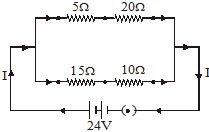
Q.33 If a 12 V battery is connected to the arrangement of resistances given in Fig. (with 5 W replaced by 10 W, 15 W replaced by 5 W and 10 W replaced by 25 W). Calculate (i) the total effective resistance of the arrangement and (ii) the total current flowing in the circuit. [2005]
Q.34 Two electric lamps of 100 W and 25 W respectively are joined in parallel to a supply of 200 V. Calculate the total current flowing through the circuit. [2005]
Q.35 Two identical resistors, each of resistance 2 W, are connected in turn (i) in series, and (ii) in parallel, to a battery of 12 V. Calculate the ratio of power consumed in the two cases. [2005]
Q.36 Two identical resistors, each of resistance 10 W are connected in (i) series, and (ii) in parallel, in turn to a battery of 10 V. Calculate the ratio of power consumed in the combination of resistors in the two cases. [2005]
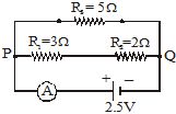
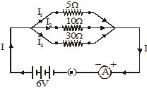
Q.37 In the given circuit, calculate (i) total resistance of the circuit, and (ii) current shown by the ammeter. [2005]
Q.38 (i) Draw a schematic diagram of a circuit consisting of a battery of five 2 V cells, a 5 W resistor, a 10 W resistor and a 15 W resistor, and a plug key, all connected in series. [2006]
(ii) Calculate the current passing through the above circuit when key is closed.
Q.39 In a household, 5 tube lights of 40 W each are used for 5 hours and an electric press of 500 W for 4 hour each day. Calculate the total energy consumed by the tube lights and press in a month of 30 days. [2006]
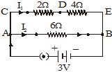
Q.40 In the circuit shown in Fig., calculate : (a) total resistance in arm CE, (b) total current drawn from the battery, and (c) current in each arm, i.e., AB and CE of the circuit. [2006]
Q.41 (a) What is meant by 'Electric Resistance' of a conductor? [2007]
(b) A wire of length L and resistance R is stretched so that its length is doubled and area of cross· section is halved. How will its : (i) resistance change ?
(ii) resistivity change ?
Q.42 (a) State Ohm's law. [2007] (b) Draw a schematic diagram of the circuit for studying Ohm's law.
Q.43 Two lamps, one rated 60 W at 220 V and the other 40 W at 220 V, are connected in parallel to the electric supply at 220 V. [2008]
(a) Draw a circuit diagram to show the connections.
(b) Calculate the current drawn from the electric supply.
(c) Calculate the total energy consumed by the two lamps together when they operate for one hour.
Q.44 (a) Distinguish between the terms 'overloading' and 'short-circuiting' as used in domestic circuits. [2008]
(b) Why are the coils of electric toasters made of an alloy than a pure metal ?
Q.45 For the circuit shown in Fig., calculate (a) the value of current through each resistance [2008]
(b) the total current in the circuit
(c) the total effective resistance of the circuit.
Q.46 (a) Express Ohm's law by a mathematical formula. [2004]
(b) Draw a circuit diagram to verify Ohm's law.
(c) Present the relationship between the voltage applied across a conductor and the current flowing through it graphically.
Q.47 State Ohm's law. Express it mathematically. Define SI unit of resistance. Derive an expression for the equivalent resistance of three resistors R1, R2 and R3 connected in series (or in parallel). [2004]
Q.48 (a) Express Ohm's law both by a mathematical formula and by a graph line. [2004]
(b) State SI units of
(i) resistance and
(ii) resistivity.
(c) What will be the equivalent resistance of two resistors R1 and R2
(i) connected in series and
(ii) connected in parallel.
Q.49 (a) What is meant by saying that the potential difference between two points is 1 volt? Name a device that helps to measure the potential difference across a conductor. [2008]
(b) Why does the connecting cord of an electric heater not glow hot while the heating element does ?
(c) Electrical resistivities of some substances at 20°C are given below:
Silver 1·60 × 10–8 W m
Copper 1·62 × 10–8 W m
Tungsten 5·20 × 10–8 W m
Iron 10·0 × 10–8 W m
Mercury 94·0 × 10–8 W m
Nichrome 100 × 10–6 W m
Answer the following questions in relation to them :
(i) Among silver and copper, which one is a better conductor? Why ?
(ii) Which material would you advise to be used in electrical heating devices ? Why ?
Q.50 (a) Name an instrument that measures electric current in a circuit. Define the unit of electric current. [2008]
(b) What do the following symbols mean in circuit diagram ?
(i) ![]() (ii)
(ii) ![]()
(c) An electric circuit consisting of a 0·5 m long nichrome wire XY, an ammeter, a voltmeter, four cells of 1·5 V each and a plug key was set up.
(i) Draw a diagram of this electric circuit to study the relation between the potential difference maintained between the points 'X' and 'Y' and the electric current flowing through XY.
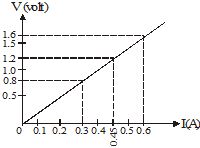
(ii) Graph shown in Fig. was plotted between V and I values.
What would be the values of V/I ratios when the potential difference is 0·8 V, 1·2 V and 1·6 V respectively? What conclusion do you draw from these values ?
· Fill in the blanks
1. If we add electrons to a body then the body becomes__________.
2. Current is a __________quantity.
3. In series circuit the current flowing throw each resistor is __________and potential difference across each will be __________.
4. The resistance offered by a cell is called __________of cell.
5. In a parallel circuit the current resistor is __________.
· Multiple choice question with one correct answers
1. A wire of resistance 40W is stretched to double its length. Its new resistance is
(A) 20W (B) 80W (C) 160W (D) 320W
2. The resistances of 200 W and 100 W bulbs of the same voltage are respectively R1 and R2. Then
(A) R1 = 2R2 (B) R2 = 2R1 (C) R2 = 4R1 (D) R1 = 4R2
3. Three resistances of 2, 3 and 5W cell connected in parallel to a 10 V battery of negligible internal resistance. The potential difference across the 3W resistance will be
(A) 2V (B) 3V (C) 5V (D) 10V
4. Two bulbs marks 25W–220V and 100W–220V are connected in series with a 440 V supply. Which of the bulbs will fuse?
(A) 100 W bulbs (B) 25 W bulb (C) neither (D) both
· Assertion & Reason
Instructions: In the following questions as Assertion (A) is given followed by a Reason (R). Mark your responses from the following options.
(A) Both Assertion and Reason are true and Reason is the correct explanation of ‘Assertion’
(B) Both Assertion and Reason are true and Reason is not the correct explanation of ‘Assertion’
(C) Assertion is true but Reason is false
(D) Assertion is false but Reason is true
1. Assertion: Current is a vector quantity
Reason: Current is charge flowing per unit time.
2. Assertion: Current flows from positive to negative terminal of the battery
Reason: This is the conventional direction of current.
3. Assertion: The resistance of a conductor is proportional to the square of its length
Reason:
4. Assertion: Resistivity changes when conductor is stretched or contracted.
Reason: Resitivity is a material property
5. Assertion: Kirchoff’s current law states that the net current at a junction is zero.
Reason: This law is based on the conservation of charge principle.
· Match the following (one to one)
Column-I and column-II contains four entries each. Entries of column-I are to be matched with some entries of column-II. Only One entries of column-I may have the matching with the some entries of column-II and one entry of column-II Only one matching with entries of column-I
1. Column I Column II
(A) Ohms law (P) Series combination
(B) Req = R1 + R2+....+Rn (Q) Terminal potential difference
(C) V = E – Ir (R) V = IR
(D) (S) Parallel combination
· Multiple choice question with one correct answers
1. A 220V–100 W bulb is connected to a supply of 110 V. The power dissipated will be
(A) 100 W (B) 50 W (C) 25 W (D) 2 W
2. A wire of resistance R is cut into ten equal parts which are then joined in paralle. The new resistance is
(A) 0.01 R (B) 0.1 R (C) 10R (D) 100R
3. A 90 W, 30 V bulb is run on a 120V supply. For this, a wire is connected in series with the bulb. The resistance of the wire is
(A) 10 W (B) 20 W (C) 30 W (D) 40 W
4. Four wires of equal lengths, each of resistance 5 W are joined to form a square. The equivalent resistance between two diagonally opposite corners of the square is
(A) 5 W (B) 10 W (C) 20 W (D) 5/4 W
· Multiple choice question with one or more than one correct answers
1. The terminal potential difference of a cell of EMF ‘E’ and internal resistance ‘r’ is given by the formula
(A) V = E – Ir (B) V = E (C) V = 0 (D) V = E + Ir
2. The voltage across a conductor is directly proportional to the current flowing across it under constant conditions of
(A) Pressure (B) Humidity (C) Temperature (D) Density
3. Choose all correct alternatives
(A) 1 volt × 1 coulomb = 1 joule (B) 1 volt × 1 ampere = 1 J/s
(C) 1 volt × 1 watt = 1 HP
(D) Watt-hour can be measured in terms of electron-volt
· Comprehension
A battery of EMF 10 V having internal resistance of 2W is connected to an external resistance of 3W. The battery is first in charging mode and then in discharging mode.
1. The current flowing through the external resistance is
(A) 1A (B) 3A (C) 2A (D) 10A
2. The terminal potential difference during discharging mode of battery
(A) 6V (B) 2V (C) 1V (D) 10V
3. The terminal potential difference during the charging mode of battery
(A) 5V (B) 10V (C) 14V (D) 9V
· Match the following (one to many)
Column-I and column-II contains four entries each. Entries of column-I are to be matched with some entries of column-II. One or more than one entries of column-I may have the matching with the some entries of column-II and one entry of column-II may have one or more than one matching with entries of column-I
1. Column I Column II
(A) Ohm’s law (P) Nichrome wire
(B) Heating effect (Q) Battery
(C) EMF (R) V = IR
(D) Terminal potential difference (S) Ohmic resistance
*****
1. Negatively 2. Scalar
3. Same, different 4. Internal resistance
5. different
1. (C) 2. (B) 3. (D) 4. (B)
1. (D) 2. (A) 3. (D) 4. (D) 5. (A)
1. (A)-(R), (B)-(P), (C)-(Q), (D)-(S)
1. (C) 2. (B) 3. (C) 4. (A)
1. (A,D) 2. (A,C) 3. (A,D)
1. (C) 2. (A) 3. (C)
1. (A)-(R,S), (B)-(P), (C)-(Q), (D)-(R,S)
1. D 2. C 3. A 4. B 5. D 6. D 7. C
8. B 9. C 10. D 11. A 12. B 13. A 14. B
15. B 16. A 17. D 18. B 19. B 20. B 21. D
22. D 23. C 24. B 25. B 26. D 27. D 28. D
29. D 30. C 31. B 32. C 33. B 34. D 35. B
36. A 37. A 38. A 39. D 40. D 41. C 42. A
43. C 44. B 45. A 46. D 47. B 48. C 49. A
50. D 51. A 52. A 53. D 54. B 55. C 56. C
57. C 58. C 59. B 60. C