Worked Out Example
15. A capacitor of capacitance C is charged by connecting it to a battery of emf e. The capacitor is now disconnected and reconnected to the battery with the polarity reversed. Calculate the heat developed in the connecting wires.
Sol. When the capacitor is connected to the battery, a charge Q = Ce appears on one plate and – Q on the other. When the polarity is revered, a charge – Q appears on the first plate and +Q on the second. A charge 2Q, therefore passes through the battery form the negative to the positive terminal. The battery does a work.
W = (2Q)e = 2 Ce2
in the process. The energy stored in the capacitor is the same in the two cases. Thus, the work done by the battery as heat in the connecting wires. The heat produced is ,therefore, 2Ce2.
16. An uncharged capacitor is connected to a battery. Show that half the energy supplied by the battery is lost as heat while charging the capacitor.
Sol. Suppose the capacitance of the capacitor is C and the emf of the battery is V. The charge given to the capacitor is Q = CV. The work done by the battery is
W = QV
The battery supplies this energy. The energy stored in the capcitor is
U = 1/2 CV2 = 1/2 QV.
The remaining energy QV – 1/2 CV2 =QV is lost as heat.
Thus, half the energy supplied by the battery is lost as heat.
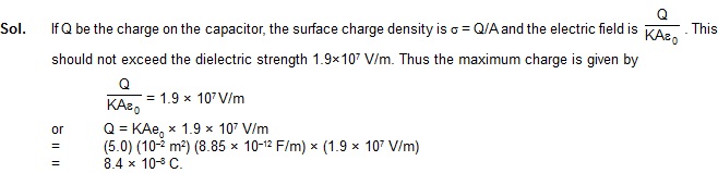
17. A parallel-plate capacitor having plate area 100 cm2 and separation 10 mm holds a charge of 0.12 muC when connected to a 120 V battery. Find the dielectric constant of the material filling the gap.
18. A parallel-plate capacitor is formed by two plates, each of area 100 cm2, separated by a distance of 1 mm. A dielectric constant 5.0 and dielectric strength. 1.9×10⁷ V/m is filled between the plates. Find the maximum charge that can be stored on the capacitor without causing any dielectric breakdonw.
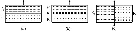
19. The space between the plates of a parallel capacitor of capacitance C is filled with three dielectric slabs of identical size as shown in figure. If the dielectric constants of the thres slabs are K1,K2 and K3 , find the new capacitance.
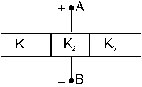
Sol. Consider each one third of the asembly as a separate capaacitor. The three positive plates are connected at A and The three negative plates are connected at B. Thus, the three capacitors are joined in parallel. As the plate area is one third of the original for each part, the capaitances of these parts will be K1C/3, K2C/3 and K3C/3. The equivalent capacitors is, therefore
Ceq = (K1 + K2 + K3).
20. Show a parallel-plate capacitor having square plates of edge a and plate-separation d. The gap between the plates is filled with a dielectric of dielectric constant K which varies parallel to an edge as K = K0 + ax.
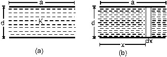
where K and a are constants and x is the distance from the left end. Calculate the capacitance.
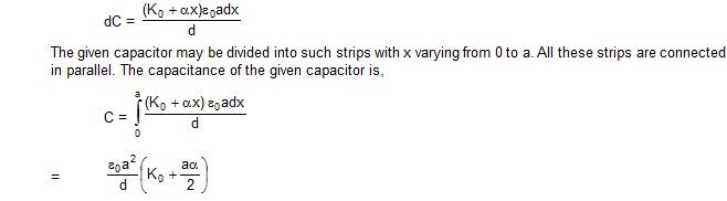
Sol. Consider a small strip of width dx at a separation x from the left end. This strip forms a small capacitors of plate area axdx. Its capacitance is
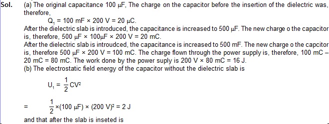
21. A parallel-plate capacitance 100muF is connected to a power supply of 200 V. A dielectric slab of dielectric constant 5 is now inserted into the gap between the plates. (a) Find the extra charge flown through the power supply and work done by the supply. (b) Find the change in the electrostatic energy of the electric field in the capacitor.
![]()
Thus the energy is increased by 8J.
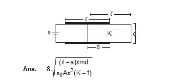
22. Figure shows a parallel-plate capacitor with plates of width b and length l. The separation between the plates is d. The plates are rigidly clamped and connected to a battery of emf V. A dielectric slab of thickness d and dielectric constant K is slowly inserted between the plates. (a) Calculate the energy of the system when a length x of the slab is introduced into the capacitor. (b) What force should be applied on the slab to ensure that it goes slowly into the capacitor? Neglect any effect of friction or gravity.
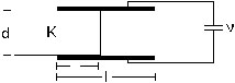
Sol. (a) The plate area of the part with the dielectric is bx. Its capacitance is
C1 = Ke0bx/d
Similarly, the capacitance of the part without the dielectric is
C2 = e0b(1-x)/d
These two parts are connected in parallel. The capacitance of the system is, therefore.
C = C1 + C2
= e0b/d [l + x(K – 1)] ..... (i)
The energy of the capacitor is
U=1/2 CV2 = [l + x(K – 1)]
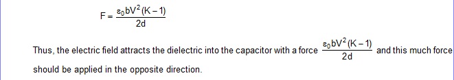
(b) Suppose, the electric field attracts the dielectrc slab with a force F. An external force of equal magnitude F should be applied in opposite direction so that the plate moves slowly (no acceleration).
Consider the part of motion in which the dielectrc moves a distance dx further inside the capacitor. The capacitance increases to C + dC. As the potential difference remains constant at V, the battery has to supply a further charge
dQ = (dC) V
to the capacitor. The work done by the battery is, therefore,
dWb = VdQ = (dC) V2.
The external force F does a work
dWe = (–F dx)
during the displacement. The total work done on the capacitor is
dWb + dWe = (dC) V2 –Fdx.
The should be equal to the increase dU in the stored energy. Thus,
1/2 (dC)V2 = (dC)V2 – Fdx
or, F = 1/2 V2 dC/dx
Using equation (i)
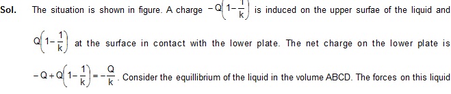
23. A parallel-plate capacitor is placed in such a way that its plates are horizontal and the lower plate is dipped into a liquid of dielectric constant K and density r. Each plate has an area A. The plates are now connected to a battery which supplies a positive change of magnitude Q to the upper plate. Find the rise in the level of the liquid in the space between the plates.
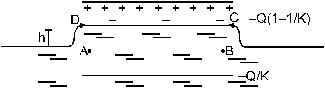
(A) the force due to the electric field at CD,
(B) the weight of the liquid.
(C) the force due to atmospheric presurre and
(D) the force due to the pressure of the liquid below AB.
As AB is in the same horizontal level as the outside surface, the pressure here in the same as the atmospheric pressure. The forces in (C) and (D), therefore, balance each other. Hence, for equilibrium, the forces in (A) and (B) should balance each other.
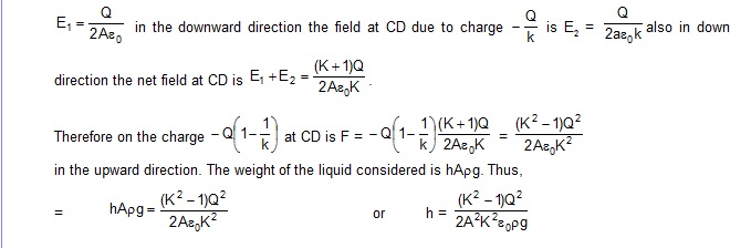
The electric field at CD due to the charge Q is
Exercise
1. When 1.0 ×10¹² electron are transferred from one conductor to another, a potential of 10 V appears between the conductors. Calculate the capacitance of the two-conductor system. [Ans. 1.6 × 10⁻⁸ F]
2. The plates of a parallel capacitor are made of circular discs of radii 5.0 cm each. If the separation between the plates is 1.0 mm, what is the capacitance ? [Ans. 6.95 × 10⁻⁵ muF]
3. Suppose, one wishes to contruct a 1.0 F capacitor using circular discs. If the separation between the discs be kept at 1.0 mm, what would be the radius of the discs ? [Ans. 6 km]
4. A parallel-plate capacitor having plate area 25 cm2 and separation 1.00 mm is connected to a battery of 6.0 V. Calculate the charge flown through the battery. How much work has been done by the battery during the process ? [Ans. 1.33 × 10⁻¹⁰ C, 8.0 × 10⁻¹⁰ J]
5. A parallel-plate capacitor has plate area 25.0 cm2 and a separation of 2.00 mm between the plates. The capacitor is connected. The capacitor is connected to a battery of 12.0 V. (a) Find the charge on the capacitor. (b) The plate separation is decreased to 1.00 mm. Find the extra charge given by the battery to the positive plate. [Ans. (a) 1.33 × 10⁻¹⁰C, (b) 1.33 × 10⁻¹⁰ C ]
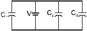
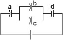
6. Find the charges on the three capacitors connected to a battery as shown in figure. Take
C1= 2.0 mF, C2 = 4.0 muF, C3 = 6.0 muF and V = 12 volt. [Ans. 24 mC, 48 mC, 72 mC]
7. Three capacitors having capacitances 20mF, 30mF and 40mF are connected in series with a 12 V battery. Find the charge on each of the capacitors. How much work has been done by the battery in charging the capacitors?
[Ans. 110 mC on each, 1.33 × 10⁻³ J]
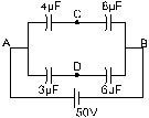
8. Find the charge appearing on each of the three capacitors shown in figure. [Ans. 48 muC on the 8 muF capacitor and 24 muC on each of the 4 muF capacitors]
9. Take C1 = 4.0 muF and C2 = 6.0 muF as shown in the figure. Calculate the equivalent capacitance of the combination between the points indicated.
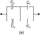
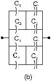
Ans. (a) 5 mF (b) 10 mF
10. Find the charge supplied by the battery in the arrangement shown in figure.
Ans. 110 muC
11. The outer cylinder of two cylindrical capacitors of capacitors 2.2 mF each, are kept in contact and the inner cylinder are connected through a wire. A battery of emf 10 V is connected through a wire. A battery of emf 10 V is connected as shown infigure. Find th toal charge supplied by the battery to the cylinder. [Ans. 44 mC]

12. Two conducing spheres of radii R1 and R2 are kept widely separated from each other. What are their individual capacitances ? If the spheres are connected by a metal wire, what will be the capacitance of the combination? Think in terms of series-parallel connections. [Ans. 4pie0 R1, 4pie0 R2; 4pie0(R1 + R2)]
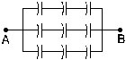
13. Each of the capacitors shown in figure has a capacitance of 2 mF. Find the equivalent capacitance of the assembly between the point A and B. Suppose, a battery of emf 60 volts is connected between A and B. Find the potential difference appearing on the individual capacitors. [Ans. 2 muF, 20 V]
14. It is required to construct a 10 mF capacitor which can be connected across a 200 V battery. Capacitors of capacitance 10 mF are available but they can withstand only 50V. Design a combination which can yield the desired result.
15. Take the potential of the point B as shown in figure to be zero. (a) Find the potentials at the point C and D. (b) If a capacitor is connected between C and D, what charge will appear in this capacitor?
[Ans. (a) 50/3 muV at each point (b) zero]
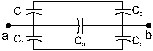
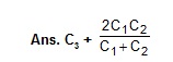
16. Find the equivalent capacitance of the system shown in figure between the point a and b.
17. A capacitor is made of a flat plate of area A and a second plate having a stair-like structure as shown in figure. The width of each stair is a and the height is b. Find the capacitance of the assembly.
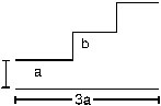
[Ans.e0A(3d2+ 6bd + 2b2/3d(d+b)(d+2b)]
18. A cylindrical capacitor is constructed using two coaxial cylinders of the same length 10 cm and radii 2 mm and 4 mm.(a) Calculate the capacitance. (b) Another capacitor of the same length is constructed with cylinder of radii 4mm and 8 mm. Calculate the capacitance.
19. A 100 pF capacitor is charged to a potential difference of 24 V. It is concected an uncharged capacitor of capacitance 20 pF. What will be the new potential difference across the 100 pF capcitor ? [Ans. 20 V]
20. Each capacitor shown in figure has a capacitance of 5.0 mF. The emf of the battery is 50V. How much charge will flow through AB if the switch S is closed?
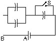
[Ans. 3.3 × 10⁻⁴ C]
21. The particle P shown in the figure has a mass of 10 mg and a charge of – 0.01 muC. Each plate has a surface area 100 cm2 one side. What potential difference V should be applies to the combination to hold the particle P in equilibrium?

[Ans. 43 m V]
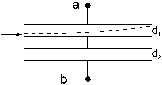
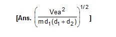
22. Both the capacitor shown in figure are made of square plates of edge a. The separations between the plates of the capacitors are d1 and d2 as shown in the figure. A potential difference V is applied between the points a and b. An electron is projected between the plates of the upper capacitor along the central line. With what minimum speed should the electron be projected so that it does not collide with any plate? Consider only the electric forces.
23. The plates of a capacitor are 2.00 cm apart. An electron-proton pair is released somewhere in the gap between the plates and it is found that the proton reaches the negative plates at the same time as the electron reaches the positive plates. At what distance from the negative plate was the pair released? [Ans. 1.08 × 10⁻⁸ cm]
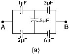
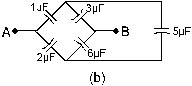
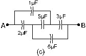
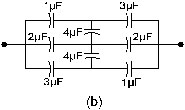
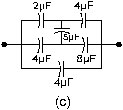
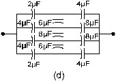
24. Convince yourself that parts (a), (b) and (c) of figure are identical. Find the capacitance between the point A and B of the assembly. [Ans. 2.25 mF]
25. Find the potential difference Vb – Va between the points a and b shown in each part of the figure.
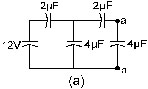
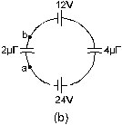
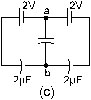
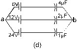
[Ans. (a) 12/11 V (b) – 8 V (c) zero (d) – 10.3 V]
26. Find the equivalent capacitances of the combinations shown in the figure between the indicated points.
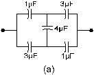
[Ans. (a) 11/6 muF (b) 11/4muF (c) 8 muF (d) 8 muF]
27. Find the capacitance of the combination as shown in the figure between A and B.
[Ans. 1 muF]
28. Find the equivalent capacitance of the infinite ladder shown in the figure between the points A and B.
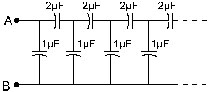
[Ans. 2 mF]
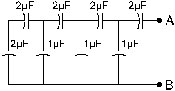
29. A finite ladder is constructed by connecting several sections of 2 mF, 4 mF capacitor combinations as shown in the figure. It is terminated by a capacitor of capacitance C. What value should be chosen for C, such that the equivalent capacitance of the ladder between the points A and B becomes independent of the number of sections in between?
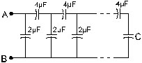
[Ans. 4 muF]
30. A charge of +2.0 × 10⁻⁸ C is placed on the positive plate and a charge of –1.0 × 10⁻⁸ C on the negative plate of a parallel-plate capacitor of capacitance 1.2 × 1.0–3 mF. Calculate the potential difference developed between th plates. [Ans. 12.5 V]
31. A charge of 20 muC is placed on the positive plate of an isolated parallel-plate capacitor of capacitance 10 muF. Calculate the potential difference developed between the plates. [Ans. 1 V]
32. A charge of 1 mC is given to one plate of a parallel-plate capacitance 0.1 mF and a charge of 2 mC is given to the other plate,. Find the potential differnece developed between the plates. [Ans. 5 V]
33. Each of the plates shown in figure has surface area (96/e0) F – m on one side and the separation between the consecutive plates is 4.0 mm. The emf of the battery connected is 10 volts. Find the magntitude of the charge supplied by the battery to each of the plates connected to it. [Ans. 0.16 muC]
34. The capacitance bewteen the adjacent plates shown in figure is 50 nF. A charge of 1.0 muC is placed on the middle plate.(a) What will be the charge on the outer surface of the upper plate ? (b) Find the potential difference developed between the upper and the middle plates. [Ans. (a) 5.50 mC (b) 10 V]
35. Consider the situation of the previous problem. If 1.0 muC is placed on the upper plate instead of the middle, what will be the potential difference between (a) the upper and the middle plates and (b) the middle and the lower plates ? [Ans. (a) 10 V (b) 10 V]
36. Two capacitances 20.0 pF and 50.0 pF are connected in series with a 6.00 V battery. Find (a) the potential difference across each capacitor and (b) the energy stored in each capacitor.
[Ans. (a) 1.71 V, 4.29 V (b) 184 pJ, 735 pJ]
37. Two capacitors of capacitances 4.0muF and 6.0 muF are connected in sereis with a 20.00 V battery. Find (a) the potential difference across each capacitor and (b) the energy stored in each capacitor.
[Ans. 960 muJ]
38. Each capacitor in the figure has a capacitance of 10 mF. The emf of the battery is 100V. Find the energy stored in each of the four capacitors.
[Ans. 8 mJ in (a) and (d), 2 mJ in (b) and (c)]
39. A capacitor with stored energy 4.0 J is connected with and identical capacitor with no electric field in between. Find the total energy stored in the two capacitors.[Ans. 2.0 J]
40. A capacitor of capacitance 2.0 mF is charged to a poential difference of 12 V. It is then connected to an uncharged capactor of capacitance 4.0 mF as shown in figure. Find
(a) the charge on each of the two capacitors after the connection,
(b) the electrostatic energy stored in each of the two capacitors and
(c) the heat produced during the charge transfer from one capacitor to the other.
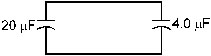
[Ans. (a) 8 muC, 16 muC (b) 16 muJ, 32 muJ, (c) 96 muJ]
41. A point charge Q is placed at the origin. Find the electrostatic energy stored outside the spherical surface of radius R centred at the origin.
42. A metal sphere of radius R is charged to a poential V. (a) Find the electrostatic energy stored in the electric field within a concentric sphere of radius 2R. (b) Show that the eleactrostatic field energy stored outside the sphere of radius 2R equals that stored within it. [Ans. (a) pie0RV2]
43. A large conducting plane has a surface charge density 1.0 × 10⁻⁴ C/m2. Find the electrostatic energy stored in a cubical volume of edge 1.0 cm infront of the plane. [Ans. 5.6 × 10⁻⁴ J]
44. A parallel-plate capacitor having plate area 20 cm2 and seperation between the plates 1.00 mm is connected to a battery of 12.0 V. the plates are pulled apart to increase the separation to 2.0 mm.
(a) Calculate the charge flown through the circuit during the process.
(b) How much energy is absorbed by the battery during the process ?
(c) Calculate the stored energy in the electric field before and after the process.
(d) Using the expression for the force between the plates, find the work done by the person pulling the plates apart.
(e) Show and justify that no heat is produced during this transfer of charge as the separation is increased.
[Ans. (a) 1.06 × 10⁻¹⁰ C (b) 12.7 × 10⁻¹⁰ J (c) 12.7 × 10⁻¹⁰ J, 6.35 × 10⁻¹⁰ J (d) 6.35 × 10⁻¹⁰ J]
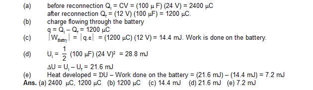
45. A capacitor having a capacitance of 100 mF is charged to a potential difference of 24V. The charging battery is disconnected and the capacitor is connected to another battery of emf 12V with the positive plate of the capacitor joined with the positive terminal of the battery.
(a) Find the charges on the capacitor before and after the reconnection.
(b) Find the charge flown through the 12 V battery
(c) Is work done by the battery or is it done on the battery? Find its magnitude.
(d) Find the decrease in electrostatic field energy.
(e) Find the heat developed during the flow of charge after reconnection.
Sol. 

46. Consider the situation shown in the figure. The switch S is open for a long time and then closed. (a) Find the charge flown through the battery when the switch S is closed. (b) Find the work done by the battery. (c) Find the change in energy stored in the capacitors. (d) Find the heat developed in the system.

[Ans. (a) Ce/2, (b) Ce2/2 (c) Ce2/4 (d) Ce2/4]
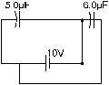
47. A capacitor of capacitance 5.00 mF is charged to 24.0 V and another capacitor of capacitance 6.0 mF is charged to 12.0 V. (a) Find the energy stored in each capacitor. (b) The positive plate of the first capacitor is now connected to the negative plate of the second and vice versa. Find the new charges on the capacitors. (c) Find the loss of electrostatic energy during the process. (d) Where does the energy go? [Ans. (a) 1.44 mJ, 0.432 mJ (b) 21.8 muC, 26.2 muC, (c) 1.77 mJ]
48. A 5.0 mF capacitor is charged to 12 V. The positive plate of this capacitor is now connected to the negative terminal of a 12 V battery and vice versa. Calculate the heat developed in the connecting wires. [Ans. 1.44 mJ]
50. If the above capacitor is connected across a 6.0 V battery, find (a) the charge supplied by the battery, (b) the induced charge on the dielctric and (c) the net charge appearing on one of the coated surfaces.
[Ans. (a) 8.5 nC (b) 6.4 nC (c) 2.1 nC]
51. The sepeation between the plates of a parallel-plate capacitor is 0.500 cm and its paltea rea is 100 cm2. A 0. 400 cm thick metal plate is inserted into the gap with its faces parallel to the plates. Show that the capacitance of the assembly is independent of the position of the metal plate within the gap and find its value. [Ans. 88 pF]
52. A capacitor stores 50 mC charge when connected across a battery. When the gap between the plates is filled with a dielectric, a charge of 100 mC flows through the battery. Find the dielectric constant of the material inserted. [Ans. 3]
53. A parallel-plate capacitor of capacitance 5 mF is connected to a battery of emf 6 V. The separation between the plates is 2 mm. (a) find the electric field between the paltes. (b) Find the electric field between the plates. (c) A dielectric slab of thickness 1 mm and dielectric constant 5 is inserted into the gap to occupy the lower half of it. Find the capacitance of the new combination. (d) How much charge has flown through the battery after the slab is inserted ?
[Ans. (a) 30 µC (b) 3 × 10³ V/m (c) 8.3 µF (d) 20µC]
54. A parallel-plate capacitor has plate are 100 cm2 and plate separation 1.0 cm. A glass plate (dielectric constant 6.0) of thickness 6.0 mm and an ebonite plate (dielectric constant 4.0) are inserted to fill the space between the plates of the capacitor. Find the new capacitance. [Ans. 44 pF]
55. A parallel-plate capacitor having plate area 400 cm2 and separation between the plates 1.0 mm is connected to a power supply of 100 V. A dielectric slab of thickness 0.5 mm and dielectric constant 5.0 is inserted into the gap. (a) Find the increase in electrostatic energy. (b) If the power supply is now disconnected and the dielectric slab is taken out, find the further increase in energy. (c) Why does the energy increase in inserting the slab as well as in taking it out ? [Ans. (a) 7.1 µJ (b) 35.4 µJ]
56. Find the capacitances of the capacitors shown in figure. The plates area is A and the separation between the plates is d. Different dielectric slabs in a particular part of the figure are of the same thickness and the entire gap between the plates is field with the dielectric slabs.

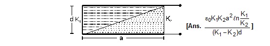
57. A capacitor is formed by two square metal-plates of edge a, separted by a distance d. Dielectrics of dielectric constants K1 and K2 are filled in the gap as shown in figure. Find the capacitance.
58. As shown in figure two identical parallel plate capacitors connected to a battery through a switch S. Initially, the switch is closed so that the capacitors are completely charged. The switch is now opened and the free space between the plates of the capacitors is filled with a dielectric of dielectric constant 3. Find the ratio of the initial total energy stored in the capacitors to the final total energy stored.
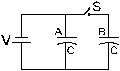
Sol. initial energy sored = UAi = 1/2 CV2 = Ubi = U(say)
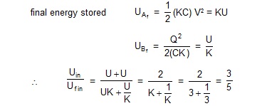
Ans. 3 : 5
59. A parallel-plate capacitor of plate area A and plate separation d is charged to a potential difference V and then the battery is disconnected. A slab of dielectric constant K is then inserted between the plates of the capacitor so as to fill the space between the plates. Find the work done on the system in the process of inserting the slab.
Ans. e0AV2 /2d[1/K-1]
60. A capacitor having a capacitance of 100 mF is charged to a potential difference of 50 V. (a) What is the magntidue of the charge on each plate ? (b) The charging battery is disconnected and a dielectric of dielectric constant 2.5 is inserted. Calculate the new potential difference between the plates. (c) What charge would have produced this potential difference in absence of the dielectric slab. (d) Find the charge induced at a surface of the dielectric slab.
Ans. (a) 5 mC (b) 20V (c) 2 mC (d) 3 mC
61. A spherical capacitor is made of two conducting spherical shells of radii a and b. The space between the shells is filled with a dielectric of dielectric constant K upto a radius c as shown in figure. Calculate the capacitance.
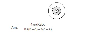
62. Consider an assembly of three conducting concentric spherical shells of radii a, b and c as shown in figure. Find the capacitance of the assembly between the points A and B.

63. Suppose the space between the two inner shells of the previous problem in filled with a dielectric of dielectric constant K. Find the capacitance of the system between A and B.
![]()
64. An air-filled parallel-plate capacitor is to be constructed which can store 12 mC of charge when operated at 1200 V. What can be the minimum plate area of the capacitor? The dielectric strength of air is 3 × 10⁶ V/m.
Ans. 0.45 m2
65. A parallel-plate capacitor with the plate area 100 cm2 and the separation between the plates
1.0 cm is connected across a battery of emf 24 volts. Find the force of attraction between the plates.
Ans. 2.5 × 10⁻⁷ N
66. Consider the situation shown in figure. The width of each plate is b. The capacitor plates are rigidly clamped in the laboratory and connected to a battery of emf e. All surface are frictionless. Calculate the value of M for which the dielectric slab will stay in equilibrium.

Ans. e0be2(K-1)/2dg
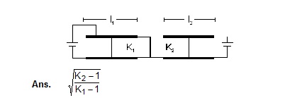
67. Figure shown two parallel plate capacitors with fixed plates and connected to two batteries. The separation between the plates is the same for the two capacitors. The plates are rectangular in shape with width b and lengths l1 and l2. The left half of the dielectric slab has a dielectric constant K1 and the right half K2. Neglecting any friction, find the ratio of the emf of the left battery to that of the right battery for which the dielectric slab may remain in equilibrium.
68. Consider the situation shown in figure. The plates of the capacitor have plate area A and are clamped in the laboratory. The dielectric slab is released from rest with length a inside the capacitor. Neglecting any effect of friction or gravity, show that the slab will execute periodic motion and find its time period.